I have a defunct F3 that I disassembled to see if I could fix it; No luck; but whilst at it I thought I’d take a look at the bottom module as one issue was that it wouldn’t charge.
The bottom module can be prised open, it has four small latches, two stainless steel and two plastic, so be careful. I opened the steel one first.
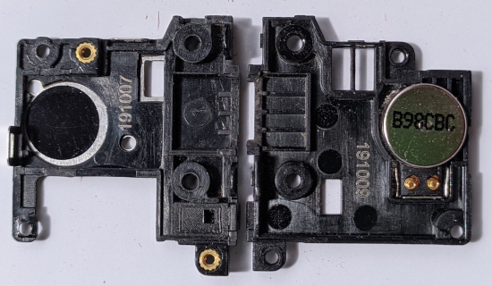
Here is the inside of the two halves of the surround. Centre is the slot for the USB C port. The shiny B98CBC is probably the vibrator motor.
It is easy to clean the area around the USB port where an amount of debris was.
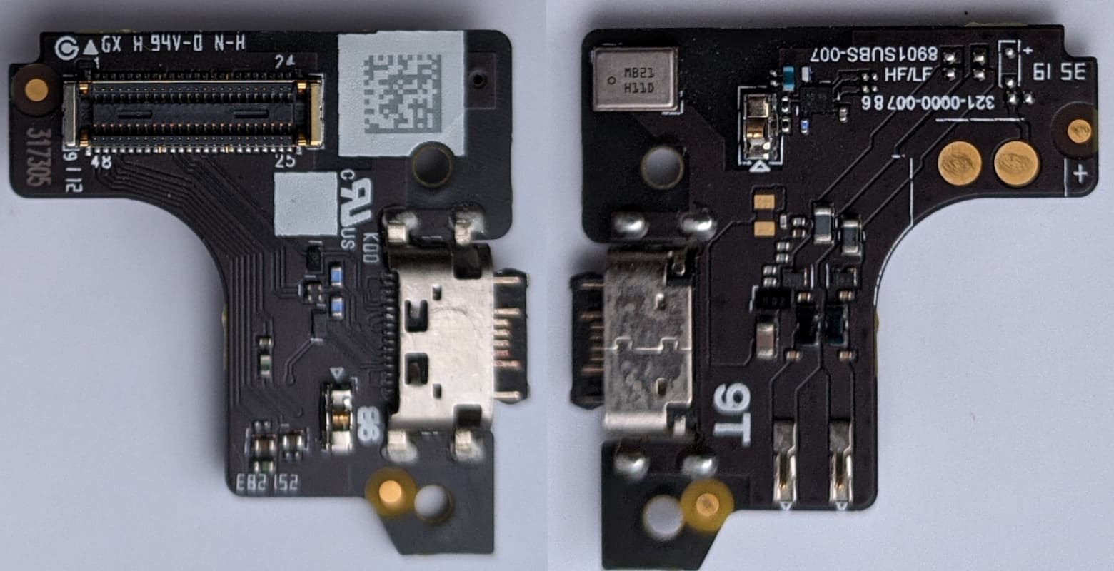
Next is an image showing both sides of the pcb positioned such that if it was flipped up from the bottom it would fit the part of the case above. It is a larger image to show more detail.
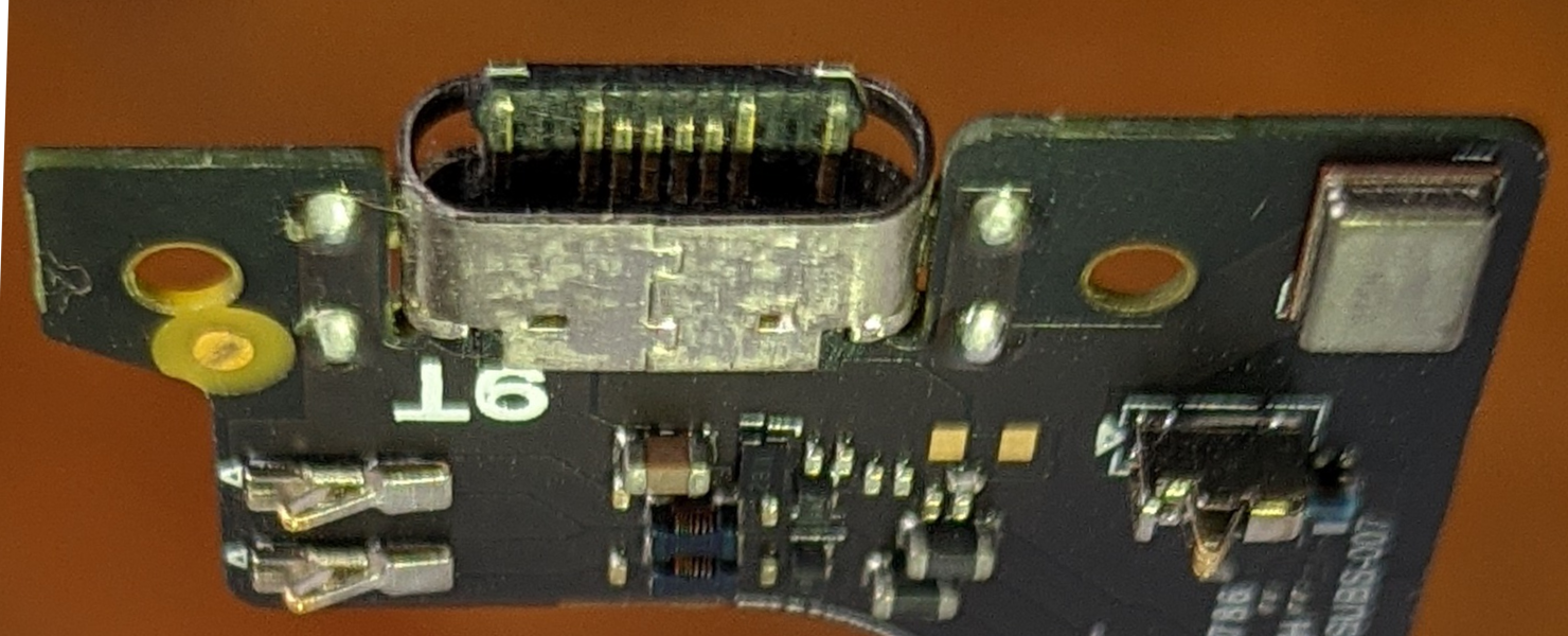
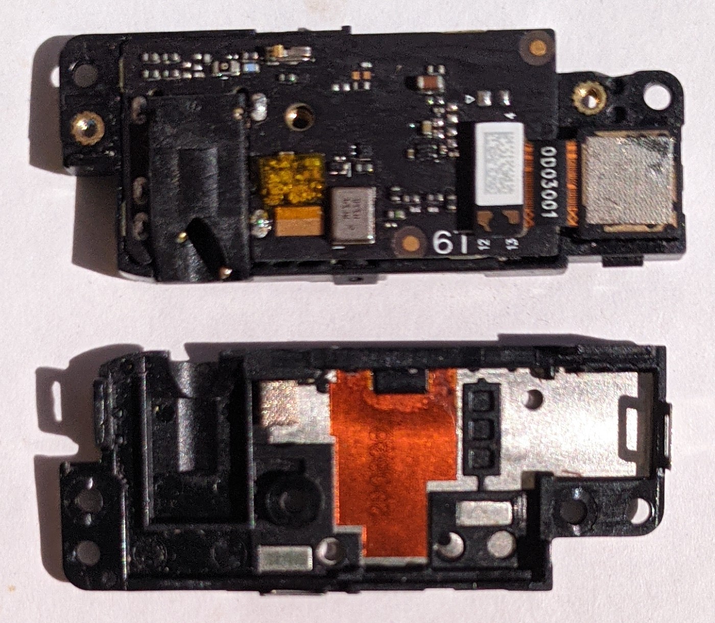
The next two images are to show more detail of the USB C connector from both sides. It’s clear there is tarnishing and the small scratches on the connectors are from me using a needle to ‘clean’ them.
Thanks! I guess the stainless steel latches are on the 9 and 12 o’clock position on the half in the left of the (1st) photo? And the plastic latches both to the right of the black empty screw channels (on each side of the USB tray)?
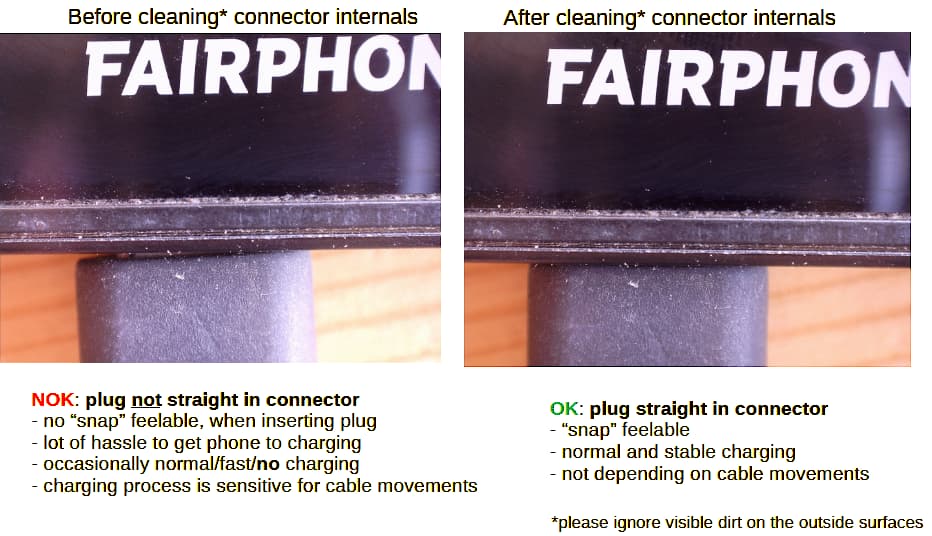
I had the issue that charging wasnt stable anymore for a long period already. Persistantly cleaning the usb-c connector did solve the problem , and prevented the need for ordering a new bottom module. Some background on the problem:
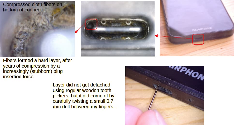
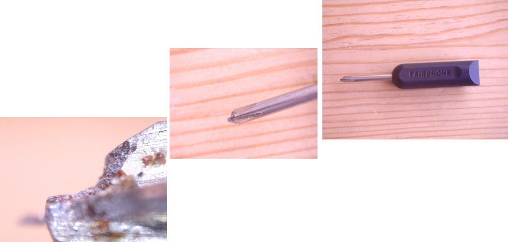
But actually, I only succeeded since I could see the fibers, using some usb microscope… otherwise I would be blindly cleaning, which also would work out in the end.