I think I broke the connector of my FP. It only charges when I push the cable slightly upwards. It does not at all connect anymore to the PC when I connect to a USB cable. I tried many different cable so that can exclude the possibility of a broken cable. I once roughly pulled the cable from the phone when I was in a hurry to leave.
I want to unsolder the connector and replace it myself. The official support option would be to replace the complete mainboard for a fee of about half the purchase price.
Can somebody tell the connector type or a compatible part number?
I now opened my FP and saw that it’s not the plug that is broken - it’s unfortunatelly the pads that are ripped from the PCB. Even though it was of course me who eventually broke it, I’m quite annoyed about the weak design of the connector. There should be some measure the prevent the bending of the connector case, or the pins should be flexible enough to not rip the pads.
I feel for you. Especially because the place is terribly difficult to solder. Got an electronics repair service somewhere near you, or do you have to do it yourself? Anyway, give us a heads up if you’ve done it.
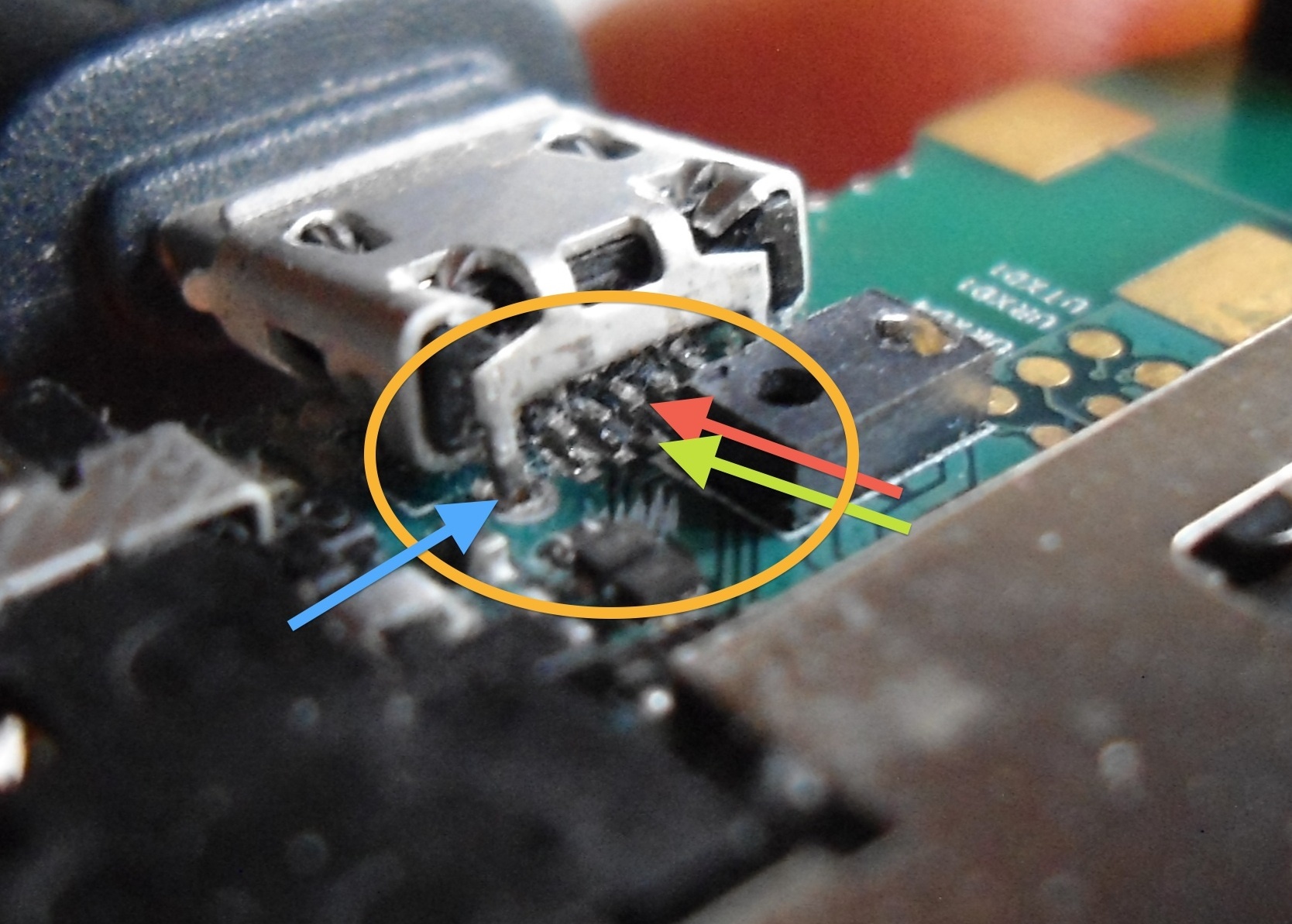
Oh, and BTW, what is this? The camera? Seen you removed it.
I followed the iFixit instruction to remove the motherboard. In step 20 when I removed the motherboard from the display assembly, the camera stuck to the display assembly and unconnected itself.
I have no idea what the component just below the connector is and how I could remove it. And how to reattach it… I would scratch off the solder stop from the signal tracks, solder them back to the connector pins, and then fill the spot with glue. It’s worth a try, because I would otherwise have to order a new motherboard anyway.
I’m on my old Nokia X3 again. The USB plug is strong with this one
Hey! Did you somehow fix it? I think i have to replace my USB connector as well. My phone fell down to the floor while still being connected with a charger and now I have to adjust pressure from the bottom in order to recharge it. So I think changing this might fix the issue. I would be happy to hear how you proceeded with your usb connector and what issues you had to deal with…
I tried to resolder the pins to the PCB, but I was not able to scratch off enough solder-stop to connect the connector pins to the tracks.
Then I tried to wire the connector pins directly to the components from wich I think the pins connect. I could solder wires to the connector, but the other components are reaaaaly small that was unsuccesful as well.
The black rectangular componet just below the connector is by the way a proximity sensor to lock your phone display when you hold your phone at your cheeck while doing a call. I removed this component during my attemps to fix the phone, but then the screen did not lock anymore. This component was absolutely impossible to be removed with a standard soldering device, because it has not touchable pins.
I’m not an absolute beginner w hen it comes to soldering, but neither perfectly experienced and equipped with tools. I think that fixing this board might be possible for a professional repair shop.
I eventually ordered a new PCB, which was about 120€ after shipment costs etc. I broke that again after a couple of weeks, also by dropping the phone while it was connected to the charger and catching it on the cable by reflex. I’ll now stay at charging the phone like in the attached picture. Since the charger connector does anyway not fit to the badly designed phone cover, I always have everything I need
I need to position the phone like in the picture, and when I shortly tip on the upper part of the phone, it starts charging. USB connection does not work for me, and for moving files from the phone I now need to use a cloud service (copy.com works fine for me).
This all is quite inconvenient, but is works fine I don’t want to buy my third PCB that I’m afraid to break again. But when I will do that at some point, I will add a drop of super glue between the pins of the USB connector.
Have the cable loading problem as well and USB does not connect at all any more to my computer.
How can I send recorded audio files to a computer? I did not find any ‘sending’ with or uploading button in the app. Does somebody has a solution to this?
bluetooth file transfer (presuming your computer has bluetooth)? Various apps for this, e.g. Airdroid - I would be surprised if they doesn’t find this kind of audio file formats.
Or send them as e-mail attachments if there are just a few of them.
I hope my reply can help you even if your post is a bit old now!
It happens the same to me. The USB connector did not work anymore and it charged only in that position.
I’ve opened the phone and discovered that the PCB tracks soldered to the three central USB pins were broken (but you can still have some contact pushing the pins downward pushing the connector like you did).
I solved this way (with the help of a professional microscope and the help of my solder-wizard Fabio M.:
We have:
removed the connector by unsoldering the remaining two lateral pins and the four ground pins.
Cleaned the PCB from soldering tin
I ordered a new USB connector from Farnell (the old one was probably usable but I preferred to buy a new one for less that 2 euros)
the old PCB tracks were not usable anymore so he has soldered three small wires on the central pins and then soldered them to the three resistors to the left of the connector (see picture).
remount everything and I got it! My Fairphone was back!
Hi Nicedears, excellent work. But as the previous poster has said, would be very usefull if you could post the code for the component on Farnell. They have a bewildering array of components on sale there. Thanks.
Nice, thanks, but unfortunately this is beyond my skills and two repair companies refused to do this as well. I guess new motherboard is the only option for me…
Maybe you find someone here on the forum, who lives near you and can help. If you want to try it, you can open a new thread (use the button “Reply as linked Topic” next to a post) in the Repair category of the forum.
I have done exactly this too Is very annoying to have to prop your phone just right to get it to charge Hurry up FP2… (and please have a stronger connector)
Well, in this case you should definitely qualify for a warranty repair. Contact Fairphone support and describe the problem, I think you will be offered a free repair immediately. Geht auch auf deutsch.