FP2 microphone repair (work in progress)

Edit: see following posts for updates - this particular fix doesn’t seem to last, but I’m trying out something different. If it works I’ll hide the text below in a spoiler tag and write a new post.

Frustrated as I am at having to wait for parts to fix my Super Nintendo, I thought I’d finally take an in-depth look at some of the broken FP2 bottom modules I have lying around. I’ve never encountered a broken USB port but I have about half a dozen of these things with malfunctioning microphones. Terrible crackling sound that can be temporarily ameliorated by twisting and bending the phone just so. I tried a whole bunch of things to improve mic performance but got nowhere - until I did.

I’d say this is an easy fix though you will need a soldering iron and some solder.

You have to take apart the bottom modules down to the two shell parts and the internal PCB, which has to be pried out of the shell very carefully so as not to bend it too far. Tricky but not hard.

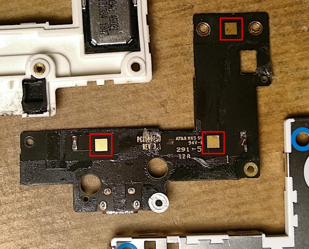
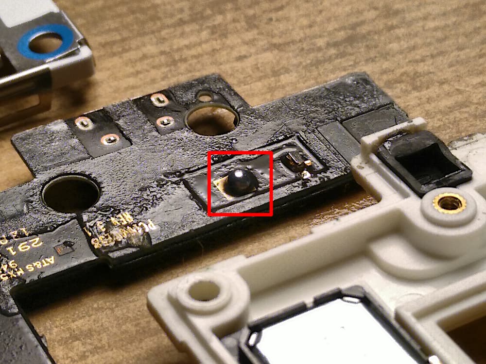
Once you have freed the PCB, you’ll see these three gold squares. They’re supposed to contact the metal shield that sits on the outside of the module through these little metallic sponges. In the two modules I’ve fixed so far, those sponges look all the worse for wear and so the PCB isn’t making good contact - or so I figure, because putting a small blob of solder on each of these three squares and reassembling the module* fixes the mic issues completely. I can flex and bump the phone until the cows come home but the microphone works flawlessly.

Some flux on the pad to make things easy, then some solder. Not too much or the module won’t close, but enough that I can see the metal shield bulge up ever so slightly when the module’s reassembled - so I know there’s contact.

I’ll test the durability of this fix, after which I’ll hopefully be able to repair all the bottom modules I still have, so I can give them away to needy FP2 users. In the meantime, give it a try at your own risk, in the full knowledge that you’re voiding any warranty that may still remain and may set fire to your phone and/or house.

* Don’t worry about the glue that was holding the PCB in place, I’ve been using one without the glue for a year now and it works fine. Just stick it back down as good as you can and you’re golden.

UPDATE: I found a total of 12 bottom modules in my big Fairphone treasure chest. Of those, four worked, three had completely nonfunctional microphones and five had the noisy mic problem. The three nonfunctional ones did not respond to this treatment - same as they were. The scratchy ones all work now. I’m testing one of these in my own FP2 to see if it lasts, and I’m giving one to a friend with a broken module tonight. If they last the week I’ll start giving them away, and hopefully I’ll be able to get my hands on more broken modules.
21 Likes

Hi As all the FP2 are beyond warranty and there are no more bottom modules, is it necessary to say it voids the warranty.

Nice job by the way

For those interested see also

and

3 Likes

I think there may still be warranty repairs for the refurbished FP2s, but as I can’t be bothered to look it up I thought I’d cover my bases.

5 Likes

So good to see DIY repairs :slight_smile:

2 Likes

The warranty covers modules purchased individually, too. End of sales for the module itself was the end of March 2021 … End of sales FP2 bottom module

5 Likes

Wow, will try that when I find the time.

Just a question: I don’t know if you can still test this, or someone else, but I have one like this, and I discovered that plugging a cable in it and pulling the cable upwards made the mic have a good contact and record, so I can record with it with a cable pushed upwards. Does this workaround work for anyone else?

1 Like

I have one with a broken mic, not sure it’s completely dead. Can test, however, not sure that I really understand what you’re doing. You put the cable in normally and then you give a bit pressure with the cable upwards? Just wondering if this is a good advice for a daily use, as I‘m wondering if this would not break the UŚB port faster. How long/often are you doing this?

3 Likes

It makes sense that this could temporarily resolve the issue, much like twisting and squeezing the phone - by deforming the module you’re improving contact between those pads and the shield. You’re probably not doing the module any favours though, like @yvmuell suggests.

1 Like

Hello
I read your words here and I am also one of these FP2 owners with problems with the bottom module. Its now for the third time… I cannot telefone and often not send spoken messanges. I made the updates, opened it 2 times, not really better.
Also to load it is diccicult, only in the complicated positions.
But anyway, you may have one more bottom module to sell?
Thank you very much
alessandra

Yes indeed.

No worries, it’s the module I have built in my beta FP2 that I rarely use for recording, I just noticed that once. Btw., if I’m not mistaken, that’s also the module whose USB port I resoldered some time ago, so I’m wondering if this isn’t the real problem.

Also, this way I discovered that the app Simple Recorder on F-Droid can also record with the secondary mic, which isn’t the case of any other I tested, if that can help someone.

3 Likes

I’m finding that this solution doesn’t last - the solder balls push the shield outward over time and the problem reoccurs - this has happened to one of the two repaired modules that have been tested.

I’m looking at spring contacts now, so instead of a ball of solder I solder on little springy fingers that will keep contact with the shield.

So this may take a little while longer, alas.

Edit: just ordered two different leaf spring contacts, we’ll find out how well they work in a couple of days. I just scavenged some spring contacts from an unsalvageable bottom module and soldered them to a broken one, and they seem to do the trick.

Edit: they finally shipped them, I hope I can try it out tomorrow or Wednesday.

2 Likes

I am in the process of trying to repair two bottom modules. One with the USB problem and one with the microphone problem.

I started with the one with the USB problem. Since I have the module apart anyway, I figure I will be proactive and try fixing the microphone before it breaks.

Due to your experience, I had a few questions regarding the fix. I would appreciate it if you could be of assistance.

Question 1: How did you get the PCB out of the shell? I attempted to pry it out from the top, but I get the feeling it will break or get damaged if I pry too hard. I was thinking of heating it up to loosen the glue and then trying to pry it out.

I was going to put some solder on the three golden contacts as you describe above. However, in your last post you say this fix does not last.

Question 2: Would it make sense to just put a very small amount of solder on the golden contacts? From your picture and description it looks like the balls are large and push out the shield. If you just add a very thin layer of fairly flat solder (not a ball) to the contact, could this maybe make the solution last?

Question 3: You said you used some spring contacts from an old bottom module. Which ones do you mean here? Could you post a photograph of them?

Thanks!

2 Likes

I went ahead and repaired the first module. Now I am able to answer my own questions.

The answers will hopefully help anyone else who might attempt this repair.

Question 1 answer: I pried the PCB out of the shell. This was done by starting at the top and using something flat (e.g. a small screwdriver) to minimally dislodge the circuit board.

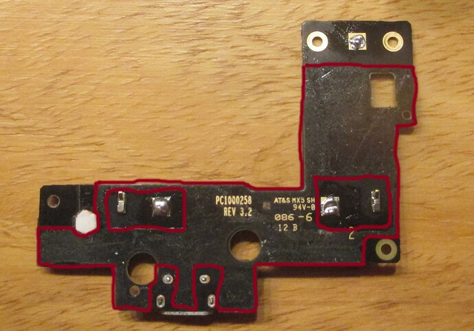
Once the upper edge or a corner is “free” enough you can just get underneath it, take a heat gun (a hair dryer will also work) and heat the PCB up to loosen the glue. The photo below shows the backside of the PCB. I drew a red line to show the areas that have glue.

This lets you know where you can move the prying tool in order to dislodge the glue, and also keep from hitting any connections or components.

Question 2 answer: As you can also see from the photograph above, I put a small amount of solder on the golden contacts.

The golden contact at the left looks like it has a big ball, but it is in fact almost flat. The two golden contacts at the right have a very thin layer of fairly flat solder (not a ball) on the contact.

The microphone works. But it is too early to say if this solution will last any longer than the one from robert.f using the balls of solder.

Hope that helps someone out there!

5 Likes

Cool! Hope it lasts. I’ve tested two so far, the first one stopped working properly and the second still works right now. I’ve ordered some of those tiny leaf springs so I’ll test those right when I get them and report back here. I’m hoping I can get to a stable, reliable fix.

3 Likes

Just to link another post reg soldering broken mic, in case it somehow helps (I’m lost with all this, so apologies if you were aware or this actually the same repair)

4 Likes

Update: I received the leaf springs, they were a little too high but they were easily cut down to fit the available space. I soldered three into a module and it works perfectly - I’ll be testing it for the next week.

And if it keeps working, I hope to finally be able to start fixing modules on a larger scale.

9 Likes

Pretty cool. I just did my first teardown, and went a bit too strong on the two metal springs, which I sheered off with my guitar pick…
Wouldn’t it have been easier to take away the metal sheet instead of pulling off the PBC plate?
Well, now I have some more soldering to do…
Where did you get the leaf springs?

1 Like

Yeah now I’m thinking I can just remove the shield, clear out the sponges, make the holes in the plastic a bit bigger and then solder in the springs.

Contact is still not that reliable, though. Sound always comes through, but it often takes some tapping and flexing to get rid of background noise.

I think I can connect all three squares with some coated wrapping wire that I then connect to the shield (or some more convenient grounding point if there is one)… That way, all contacts are soldered, so you’re no longer relying on friction. It would still necessitate a full disassembly, but it would be a solid, reliable fix at last.

I got the springs from Otronic, they’re pretty cheap. They’re small but I still needed to carve out the holes in the plastic, and they’re too high so I had to cut off part of the springs to make them depress further. But like I said, this is still not a reliable fix. I’ll try out the wire idea tomorrow and report back.

1 Like

I soldered in a wire. It runs from square to square to square and then to one of the screw holes next to the big module connector - and it works! It still took a tap to the phone to get all the noise to go so it isn’t perfect, but that probably has more to do with the amount of experimentation this particular module has been subjected to.

I’ll be testing this mod for a week, again. Hope it keeps working, but I don’t foresee any way this could fail. No longer dependent on friction, not sensitive to deformation of the module.

Protip: cheapest way to get thin coated wire is to take apart an old appliance with a transformer, or an old transistor radio with a bunch of wire wrapped inside.

5 Likes

Woah, that’s great! I will do that! Can you post a picture so that is clearer to me? But I think I got it anyway. I’ll try that!

1 Like