Hey,
just desoldered my microphone from the bottom module.
the (very thin) pcb is glued into the plastic case of the module. But with a heatgun the glue softened and you can pull it out.
After that I put my heatgun on 380°C and desoldered the mic. I coverd the surrounding parts with kapton tape.
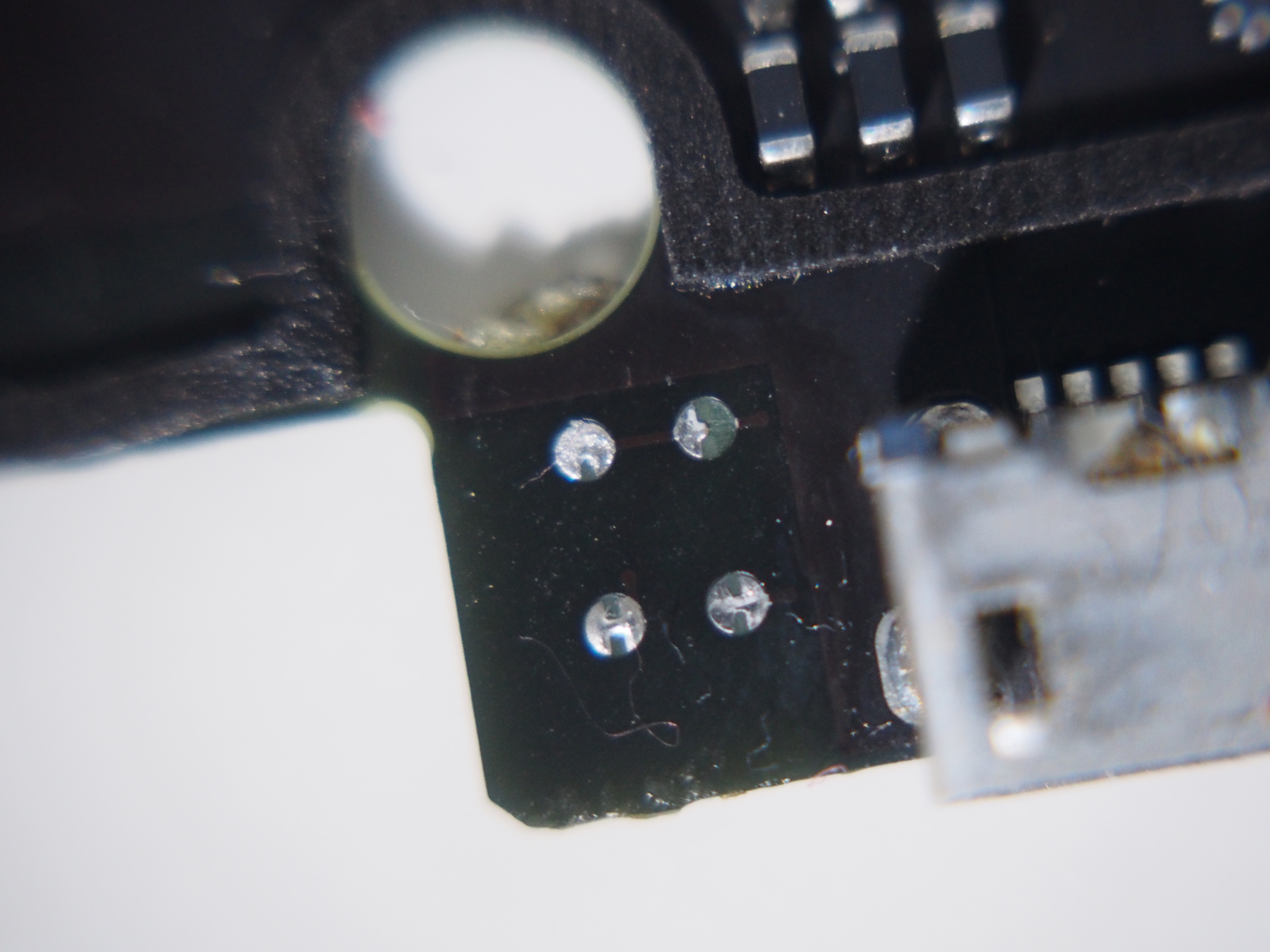
But I ripped one half of one solderpad off the pcd(see picture, top right pad). The trace from that pad seemed to be connected to a via next to it.
Jep, that happens easily with surface mounted devices. You can try to scratch away the black coat on the line and place the mic a little bit shifted to the scratched side. For a good soldering result you should use soldering paste on the solder pads.
Happy soldering
And please tell us about the result.
Hey @ElKrasso, thanks for these great photos!
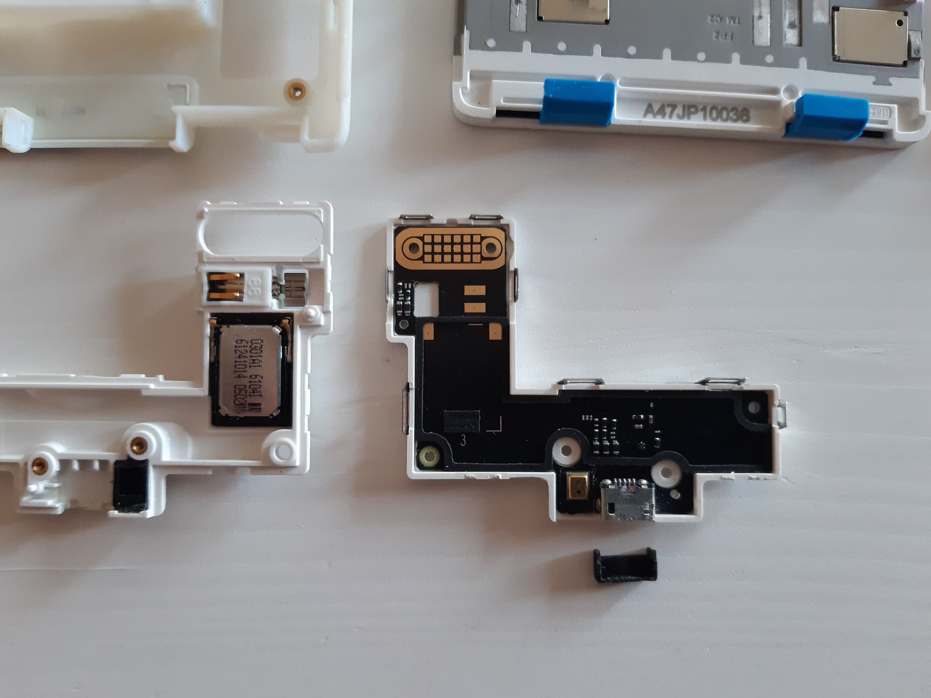
I have here a bottom module with a non-functional micro-USB port, and I thought it might be the same. I observed the port through a binocular loupe. See the result:
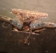
(sorry for the lousy photo, it was taken by my FP2)
It seems it is full of dirt (which couldn’t be seen without magnifying), but there are also two cracks, shown by the arrows. The don’t seem to severe to me. What do you think? I can try resoldering them, though I think my tip is also way too big and I don’t have soldering skills as good as yours.
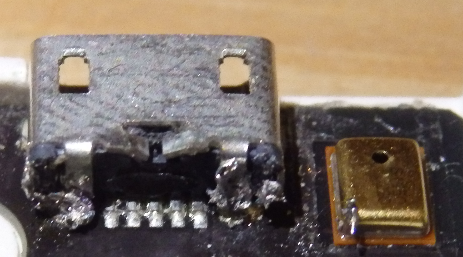
on the photo the cracked solder joint are obvious. But these are only for the shield and on both sides are additional ones.
I can not see cracked data or power conatcts. I would just resolder all contacts and give it a try. Maybe you solve the issue just with that. It is worth the try and enhance your solder skills
Is it just me, or does it look corroded at the top in the middle.
If so, it seems that the “opening” there might result in corrosion on the inside as well.
Still, worth a try and a good practice in soldering.
I had cases of compessed dirt, which prevents the plug to connect correctly to the contacts. So the charging progress was very slow or only possible when bending the plug into the socket.
At first when I tried it, it didn’t work. I wasn’t too surprised.
Then today I tried it out again. And surprise… it worked!!! I had to nudge it a bit before it accepted to charge and to be recognized by adb, but it actually worked! Now, I can’t be sure whether it’s the soldering or the dismounting that helped, though I would tend to say the soldering.
Only negative which I saw only after having remounted everything: I let a bit of tin on the mic (as you can see on the photo), and it seems to interfere with the recording sometimes (but the mic still works). I may have a look at it to remove it sometime.
Even though it was probably out of luck, I repaired my first bottom module. Let me be proud.
I also want to share my experience with repairing the microphone.
From one day to the next my microphone didn’t want to work anymore. This was not the first time but now, I can’t buy a new bottom module…
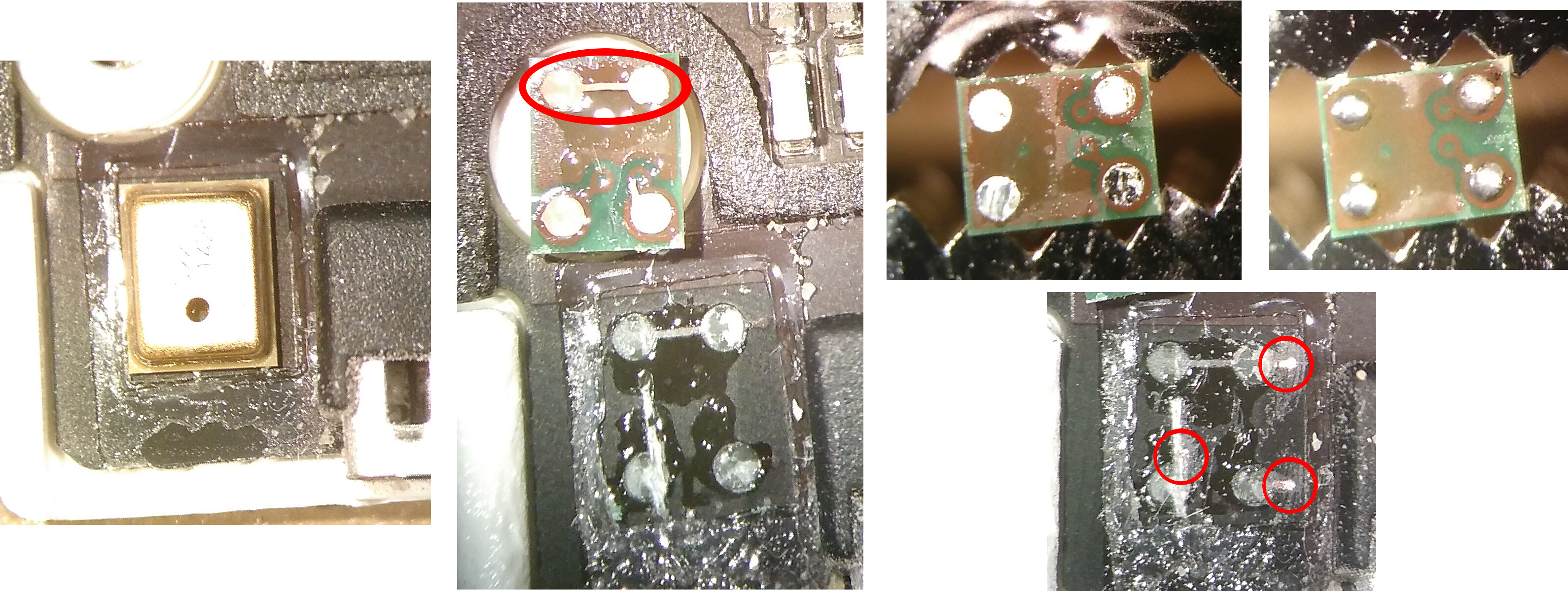
I read a few times that the pcb tracks are maybe cracked. So I opend my bottom module, heated it up to soften the glue and the solder and removed the microphone from the pcb. And the result was: All three tracks are broken (now) (see picture below)…
The solderpads of the pcb were still on the bottom side of the microphone. And as you can see, there is a short between two of the four contacts. After cleaning up and solder removing, you can see in the green pcb of the microphone, there is already a short between these two contacts. Therefore, the microphone need only 3 contacts to the board.
I scratched away the black of the three remaining tracks so that you can see the copper and you have new contactpads for soldering. The microphone contacts got new solder (a little bit too much) und flux so that there is enough which can flow to the new contactpads. I put the microphone back on the pcb, a little bit displaced so that the solder is over the new pads, heated it up and pressed it to the board.
(I hope you can see the picture. It is the first time for me to post a picture.
Also, I’m sorry for the bad quality. I took the picture with my FP2 through the ocular of a normal microscope )
How did you do that? My FP2’s microphone does not work any more. There is no waranty left, so, having not much to lose, I would like to try to repair it like you.
Currently, I’m at this point.
I don’t know how to go further.
I don’t manage to take the circuit out of its case.
Won’t I break it?
How did you do?
As you can see on my pictures I didn’t take the PCB out of its white case. But with the heat you will probably attack the case and melt it a little bit. When you are careful, a little bit of melting won’t be a problem, but you need a hot air piston so that the hot air will hit only the microphone. Otherwise I recommend to separate the PCB from the case.
Thanks for your reply.
I was impatient, I had no hot air piston, so I put the PCB and the half case in my oven.
It melt, and, as I was not careful, it melt more than few.
Well this half of case is not usable any more now, but I was able to take off the microphone.
The phone is still usable with only half a case for the bottom module and no primary mic.
I’ll try to solder the microphone some day soon.
Thanks for sharing your experience with repairing the microphone @unhawkable! I had almost missed this post of yours since the thread is about repairing the µUSB port, perhaps one of the kind mods could split the topic and title it appropriately?
I’m currently facing a similar issue with the microphone not working while the rest of the bottom module continues to function. I’m hoping it’s not the traces on the board that have cracked, that it’s only the solder on the surface mount that has cracked which can be fixed by melting it with the heat gun and letting it cool again, doing a reflow of sorts.
Are there any gotchas I should be aware of before attempting this? I assume it’s better to loosen the glue with the heat gun and remove the board from the plastic casing to avoid melting it. Did you heat up the whole board or just the area around the microphone? What temperature did you heat it up to, did it not damage the mic? (I would’ve assumed excessive heat would’ve damaged the coil found in a dynamic mic, but the FP2 may be using a piezo mic or even something completely different; is the type of mic used here known?)
I’ll be sure to report back with the results. In the (fairly likely) case that I fail, I’m already looking around for a replacement module anyway - the only reason I’m even attempting this is because they’re no longer available from the web shop.
You should remove you PCB from your plastic case to avoid any damage.
To loosen the glue of the rubber case of the mic you need a much lower temperature than for removing the mic off the board.
Usually I use a solder temperature of about 350 to 375 °C. But with this high temperature you have to be quick otherwise you could damage parts of the PCB.
There are 2 tips I can give you:
Use solder flux and don’t be economical with it (but only on the PCB not into to the mic!).
If you have a heatable board, use it. You can adjust it to about 100°C and put thc PCB on it. Then you don’t need so much heat from a heat gun to loosen the solder.


 )
)