FP2 dead - red light on constantly?

An update (and a question - of course!)

*Edit - @Leo_TheCrafter has noted that it was probably an inductor, not capacitor, so I have updated the information here to reflect that!

As an (obvious to me) warning to others. A lot of what I have done is trial and error and internet gleaned / desperation. Please do not take this information as the “right way” to do things, but hopefully you can judge for yourself by me providing my experience.

I did end up buying an Ultrasonic cleaner (sorry @Leo_TheCrafter - I’d already ordered it by the time you responded because I had a particular time deadline). I have no idea whether it made any difference. I bought https://www.amazon.co.uk/gp/product/B07GWMPVXW after noting that an electronics specialist was selling the same machine with added branding. I also bought https://cpc.farnell.com/ambersil/6330001300/ultrasonic-cleaning-liquid-1ltr/dp/SA02601 and some de-ionised water from Halfords. I basically diluted the cleaner solution with deionised water and then “cleaned” the stripped down board for 30 minutes. I then rinsed the board with more de-ionised water, then a good wash and spray with IPA cleaner (as above) before drying in the oven at 100deg C for 30 minutes. Naturally letting it cool before touching and reinstalling the board.

No luck. Same red light. However, I then looked closely at the board, and my pre-cleaning pictures and noted that a capacitor / inductor had blown (it was blown before I cleaned it - I just hadn’t spotted it). The photo shows the crack in the ceramic and the residue leaked onto the PCB.


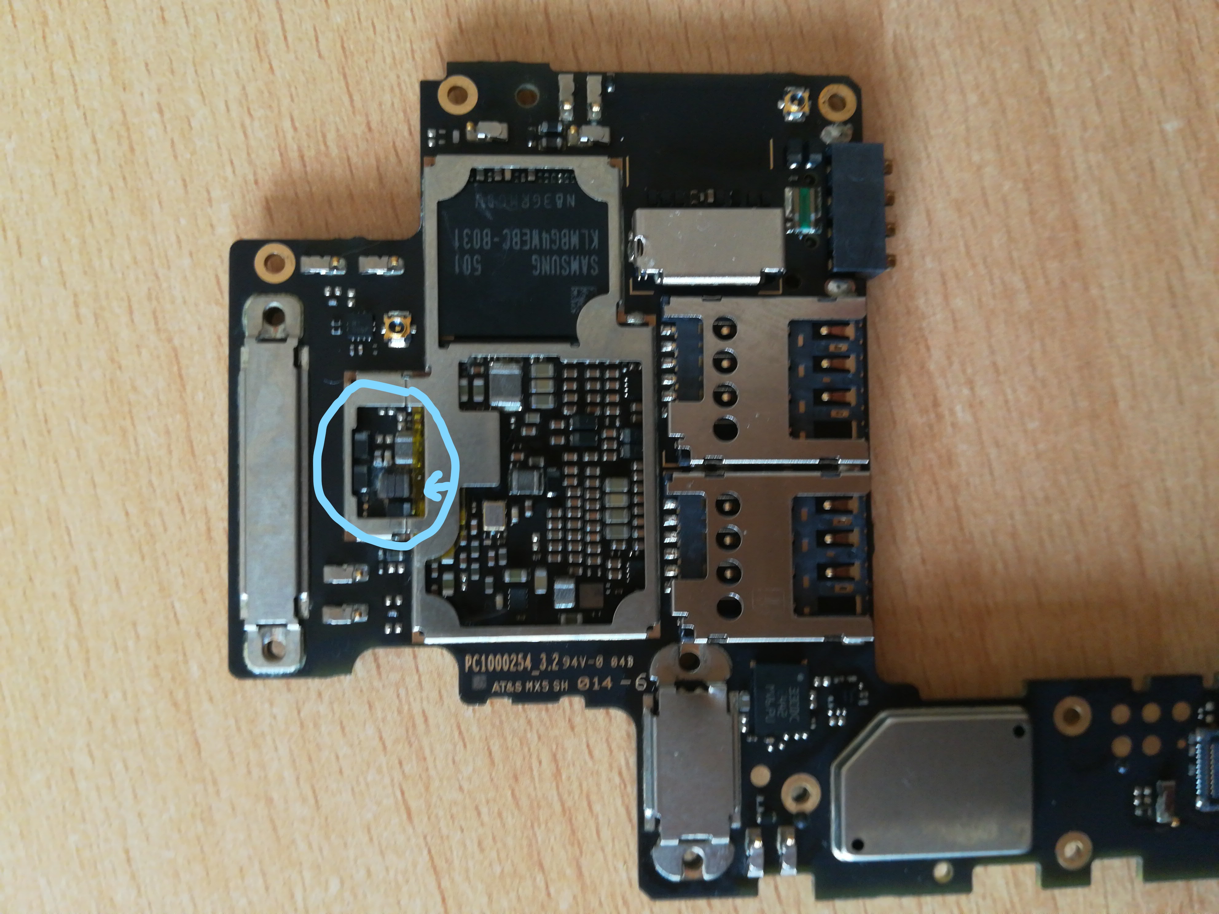
I bought a solder mop https://cpc.farnell.com/servisol/200004305-1-5mx1-5mm/soldamop-red-1-5mm-x-1-5m/dp/SASOLDAMOPSTD and tried to desolder the capacitor / inductor. I failed. I didn’t have the right tools or skills. I gently removed the cracked and failed capacitor / inductor by breaking it to pieces (not a lot of force was required). The solder joints remain, but the gap between them is as good as it being removed.
I have not replaced the capacitor / inductor. I recleaned the board as above and tried again.

Success! The phone now works and the battery drain issue has gone. Presumably this capacitor / inductor was causing a mild short circuit.


The only thing which isn’t working now, is the rear speaker. This worked after my initial success, but has obviously been damaged in the second attempt to get it to work. I have tried switching out the bottom and top modules with no success. The strange thing (to me) is that the headphone socket still works. So if I do checkup on rear speaker with headphones I can hear the Fairphone ringtone. The ear speaker and microphones both work. The audio module is therefore clearly still working. All the other bits of the bottom module are working (USB, vibration, microphone) - just not the speaker. If anyone has any suggestions where I could look for a fault I would be very grateful. @Leo_TheCrafter I note that you have just managed to design a new bottom module - are you able to point me in the direction of which pins are used to connect the speaker and where I should look for a pcb failure?


I’m going to put my pictures of disassembling the core module separately, since this post is already too long (now uploaded at Stripping down the Core Module). Any questions or hints gratefully received! The best thing is this message is being sent via my Fairphone :slight_smile:

3 Likes

I don’t think telling you the pins will give you any advatage. I only know the pins on the bottom module, not the circuit on the mainboard. I can’t say for sure, but it looks like you got rid of an inductor, not an capacitor.
Inductors are used to drive speakers, create voltages for the speaker amp and much more.
If you want, you can check the voltage at the component from a known good board.
Capacitors are usually brown, some black with a white stripe on them.
If you want, you can try checking the resistance between the two pads. If it was an inductor, it should be OL to a few kohm. There should not be a resistance to ground lower than maybe 100ohm check between ground by connecting one probe to one of the pads at a time and the other one to one of the remaining shields (SIM slot should work, too). If you have removed a capacitor there should be close to 0 ohm on one side and a few 100 to a few kohm on the other side.
If it turns out, you have accidently removed an inductor, it’s quite likely to be for the amp, to drive the speaker. The best solution would be to replace it with an inductor from a donor board, maybe check with the fairphone angels, or at you own risk, replace with a 1µH inductor of the right size. But please wait and write back before trying any of those methods, just meassure. I can give you tips on some more andvanced soldering operations.
A short rarely damages anything badly on a power ciruit (have shorted quite a few IPhones), but if sth happens, you have a paperweight, unless you can find out the exact ICs.

4 Likes

Leo - Thank you!

Ooops :blush: On the plus side the phone works now - except for the speaker. Could a shorted Inductor cause the phone to stop working? My basic understanding suggests they are supposed to conduct anyway, so I am surprised it could short circuit “more” and render the phone useless. But then I’m sure you see my electrical knowledge is limited :wink:

Interestingly, there was a long fine wire which seemed to be coiled within the component when i took it off the board. Sounds like an inductor? Sorry to sound so, um, dumb!

I assume that you mean on the board (rather than the two pads on the inductor? The component is rather fragmented, if I can even find the dust…!

Thanks again. I certainly will. I am appropriately rebuffed - I can see your eyes rolling! Things are less urgent now, so I can walk steadily to fix the final problem. I don’t think I have any fairphone angles anywhere near me (Newcastle upon Tyne, UK).

Would be gratefully appreciated. Sadly every shop that I have approached has at best directed me elsewhere, but usually been completely useless. It would appear that society’s desire to dispose of and replace has become deeply ingrained at all levels.

Really appreciate all your help @Leo_TheCrafter - an amazing support to the community. Thanks.

1 Like

For people like me, less familiar with electronic components, I found this a plain reading explanation:

http://www.differencebetween.net/technology/difference-between-capacitors-and-inductors/

If an inductor is damaged, it might be a dead short, instead of a real inductor, causing the output voltage to be unregulated, the PMIC detects that and shuts down

3 Likes

I just wanted to say: kudos, and thank you for sharing your detailed journey. This whole thread has been an interesting read, especially as a Fairphone Angel. I don’t see myself doing such though.

3 Likes

Thanks @JeroenH - I’m glad that you have found it interesting. I was determined not to create another abandoned “my phone’s broken” thread :wink:

I think it is worth remembering I definitely did not set out on this route. It started with an accident! I turned to the professionals who all turned away. I had data that I wanted and a broken phone - there wasn’t a lot to lose. I have learned a lot, but would definitely recommend a professional doing the work if you can find one that you trust!

I think the biggest thing that I have learned, is that although we all know rice is bad for wet phones, drying them out isn’t much better. (Although a little over simplified): Turn it off, remove the battery and submerge it (no, not the whole phone!) in IPA as soon as you can. This will remove the water and electrolytes. Then dry it before turning it on. I don’t think this is mentioned in any water damage guide, but is now my understanding.

All the best Angel-ing.

2 Likes

Hi Leo,

Sorry for the (huge) delay in replying. Life has had some big turns since I was last able to investigate this. I hope that COVID-19 is not causing you too much trouble.

I have followed your instructions and have measured the resistance between each of the pads and the shields.

The pad nearest the top of the board measures ~2 ohms (which appears to be as close as my meter reads to 0 ohms), the pad nearest the battery measures ~40 ohms.

These readings are from my damaged board, which is what I understood that you were advising me to check - is that correct?

From this I presume that this means it was a capacitor?

Have you any suggestions about what I could try, to see whether a component might be replaced; difficult I know, given the lack of knowledge about what the component was :wink:

With kind regards

1 Like

That was likely a capacitor. The one side with 2ohm is GND and the ~40ohm is likely some core supply for the CPU. (VCORE?)

1 Like

Thanks @Leo_TheCrafter for your quick response.

Presumably replacing this component is unlikely to change the non functioning rear speaker then. One assumes that there must be another fault somewhere that I have failed to spot?

Such a shame, since having had to use a S*ny for a few months, whenever I pick up the Fairphone I realise how light and good it is as a phone. Not to mention the root, modules etc etc. Not very usable with no rear speaker, sadly.

Any final pointers, or just recycle / fairphone angel the core module, do you think?

Many thanks for all your time and help. Extremely grateful.

Maybe meassure power rails near the caps of the audio codec. There could be sth. wrong there. If not I would think that it is the I2S between the CPU and the audio codec. You know the drill: Take off, clean, reball, solder back on, and that for CPU, RAM and the audio codec. Have fun, but it could still be some issue with the power rails. I would try that

1 Like

This topic was automatically closed 182 days after the last reply. New replies are no longer allowed.