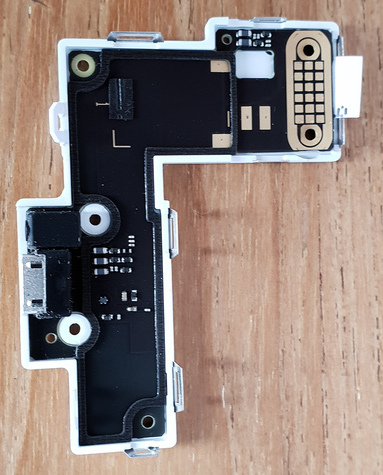
A few months, after I got my FP2, the microphone stopped working. Later, the same happened with the replacement part. And now again with the second replacement part. I don’t want to elaborate on the trouble shooting now. There are two tickets for anyone curious:
https://support.fairphone.com/hc/en-us/requests/157320
and
https://support.fairphone.com/hc/en-us/requests/216279
Now, I could keep ordering one or two new bottom modules every year or so. 25€ aren’t that much over such a period and I could order a bigger bulk to save shipping fees. But that would kinda miss the basic idea around the FP2: It would miss the point of being environmental friendly and made to last. Also, the delivery company DHL express is just shitty.
I want to try another direction: Repair the bottom module directly. I have a professional background regarding electronic circuits and experience with soldering. So there isn’t a big problem here. Everything I need is a broader understanding of this specific hardware: Which pin does what? How does the circuit inside the module look like?
I already had it opened and tried a few general things: Clean the contact pins, paint conductive lacquer onto the kinda scraped looking contact plates of the display module, cover the pins in solder tin (and clean the flux away). So far, no effect.
It made sense because at first, the mic would still work if I pressed the whole phone at the bottom centre. It just felt like a contact problem.
But after a while (before my attempt of deeper repairs) this stopped working, as well.
I’ve got a few more ideas, though:
- microscopic cracks in the conductor pathes
- cold soldering joints
- the microphone itself being damaged (even though it is unclear, why pressing made it temporarily work)
My biggest problem here is that these tiny details are hard to recognize. Using a microscope with ~50x magnification helps. But I still need to know what I am looking at. Some of the parts, I can recognize as diodes, resistors and capacitors. The microphone is under a rubbery casing. there are also some black conductor paths recognisable on a black background.
It would be extremely helpful to have some kind of circuit plan at hand to analyse further. I would also like to test the module separately, for which I need to know which pin is connected to what.
Does any of you folks here have such kind of information?
Or any alternative ideas?


