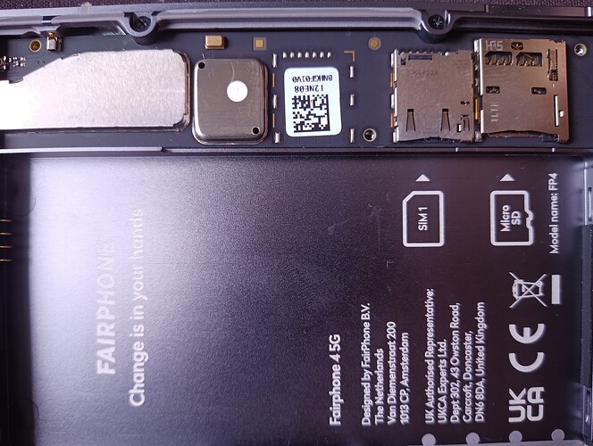
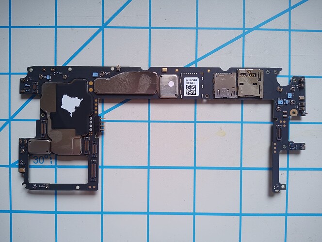
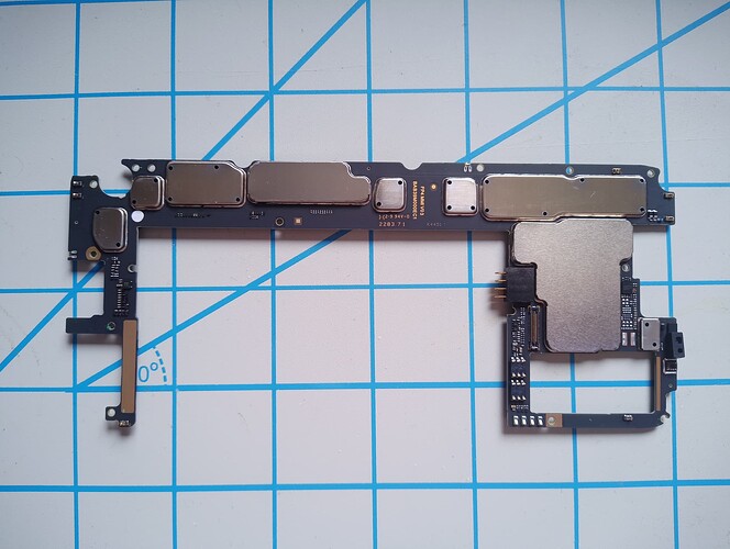
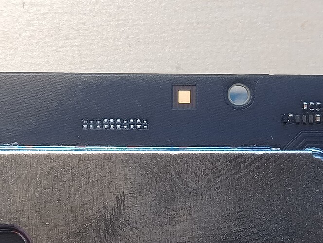
So I’ve been looking into modifying the fp4 and I found that the physical wiring is there for a second Sim slot. So is there a way to solderer on a second slot and make it work?
I know that there might be software lacking but since the physical part is there couldn’t we use a custom OS and add the software?
I have education in electrical and software engineering so I know generally how these things work but I’m still new to smartphones so I could be missing something.
Thanks for any help
Well, upfront: I cannot provide any information for you (I’m sure you are fully aware of the warranty certainly being voided once you modify the hardware like that), but I’m already grateful for your photo – first time I get to see the opened ![]() core module
core module ![]()
oh ya I’ve already done so many things that voided the warranty that at this point as long as I don’t break my phone it’s fine
This immediately begs the question: Why the fuck don’t they ship their phones with 2 sim card trays out of the box, when the hardware is cleary there?? I am very negatively surprised by this, since they purposefully made the phone worse than it could’ve been.
It might not actually be there. I can’t follow any of the lines because it’s all black so it might do nothing. But then why is it there? It’s all just really weird. My theory is that they wanted to and they put it in the prototype but for a reason had to remove it but were too far along to change the PCB. But then why did they change every other part and not this one?
Ya thanks! It’s going to take some time for me to check all of this but at a glance all the physical wiring might be there so this should work
At least on the schematics, the traces for that missing socket appear to be connected to UIM2_DATA, UIM2_CLK, UIM2_RESET (the three relevant connections to the SIM card), and UIM2_DET_N (card presence detection). These go to GPIO_75 to 78 on the SM6350 (page 36 of the pdf). The schematics actually show a KP13B-SF-PEJ(800) nano SIM socket in both SIM socket locations (page 56). That isn’t actually there in the case of the second socket, however.
However, UIM2_DATA, CLK, and RESET are also connected to a ST33G1M2 for E-SIM2 (also page 56), underneath the shield just to the left of the missing socket in your photo.
It is possible that adding the E-SIM functionality in this way would prevent the physical SIM location from working unless the E-SIM chip were disconnected. However, it’s possible that there’s some switchover, possibly based on UIM2_DET_N: whether this is doable with the SM6350, and whether it was actually implemented here, are two different questions.
Since the socket is there in the schematics, but not physically there, it’s not clear whether it is actually connected, and whether any of the related components are present. It would be useful to look on the other side of that board, and see whether components like R4601 and T4609 are present (page 31).
If they are, I suppose you could just order a KP13B-SF-PEJ(800) (it looks like Mouser and Digi-Key both have it, for ~€2), solder it there, and see if it works?
Ya that’s one of my theories, that you can only have two sims with the chip they use and the they took the second sim for the esim but for some reason never removed the wiring for the second sim.
But looking at the schematics I found that the NFC_SWP pin is connected on the sim1 to Vpp and that the sim2 doesn’t have anything connected to it. I can’t find the datasheet for the ST21NFCDDBGARA9 chip that the NFC_SWP pin is connected to but based on the name its the data line connected to the Vpp and that doesn’t make sense. I’ve already contacted product.management@fairphone.com. ( the email they give for any question on the schematics) but they haven’t answered yet.
My plan is to wait a few days to see if fairphone answer and unless they respond and tell me a good reason why I can’t do it I’m going to order the parts and try it. I’m going to first try it by just soldering on the slot and try it if it doesn’t work see if i can remove the esims because I’m not going to use esims anyways.
It would probably be worth checking on the other side of the board to see if the components for the slot are there, too. They’re on the schematic, but the sim holder is on the schematic too.
Ok so I check all the components and ya a lot are missing, this is the list;
T4609
T4608
T4601
C4607
R4607
R4606
T4607
R4601
C4605
T4611
and these aren’t in the list of components even if they’re on the diagram
So this got a lot harder but I still want to try
I think you’re on the right track. I took a brief look at the schematics of the repair PDF page 56. I looks like the second SIM holder and its peripherals are not populated, but the I/Os seem to be shared with the eSIM2 IC chip. So not sure, if these has to be cut before being able to use the second sim slot.
The Schematics in regard to the first SIM Slot seem to be very symmetrical (with the exception of the NPC_SWP pin. Maybe some sort of ChipSelect contact?) However, I think the not listed parts would be the same as for the first slot T4601,T4602,T4603,T4604,T4605 and so one.
That’s one of the dumbest things they’ve done to the FP4, together with removing the aux port. Why would you remove the possibility to use a second physical sim card if you planned for it the entire time? Nobody uses eSims, hardly any provider suports them, if you’re on holiday and want a local data card you can’t just buy a prepaid one and pop it in, it’s just so much more hassle. I have no idea who makes these decisions at FP atm but they should fire this guy.
Can you somehow proof such a general statement? In Germany e.g. most provider support them and actually Iphones are quite spread in the world…
With eSIM as frequent traveler you can even activate many eSIM and easily switch without the need to open the phone etc…
I use several eSIMs and a physical one. Being able to just switch numbers without having to shut down the phone or carrying those around is a feature I wouldn’t give up again, now that I have it.
I wouldn’t have bought the FP4 if they hadn’t included it, eSIM support is future proofing and I’ve had to stop using my (still working) previous phone because of something similar.
Even if you don’t like it, you might need it in 5 years.
Hm… Maybe it’s like with USB-C in that the technology itself is cool, but the adaptation is so subpar that it cannot live to its potential
You scan a QR-code and moments later you’ve got a new SIM in your phone, I find that very convenient.
I can get a new SIM / number in like 5 minutes as well, that’s very useful from a privacy / phone spam perspective.
Try it at some point, it’s actually quite handy ![]()
That sounds really useful and is a good reason to have it, but I still want to try this and give the option to anyone who wants to have 2 physical sim.
It’s also a cool project that is fun to figure out and givens us a better understanding of how the phone works. Which can help people in the future repair them.
I’ve already ordered all the pieces and I’m just waiting for them to start. I’ll keep all of you updated on what happens
Oh, by no means did I mean you shouldn’t carry on with this project.
I’m closely following every update, very exciting where this might go and so much learning opportunity for people who don’t know a lot about electrical engineering, like me ![]()
@Stanzi
Strange statement. Therefore I may assume you have not yet seen many electronic devices from the inside.
This is common practice.
Take a look at more electronic circuit boards and you will realize there are many more positions free where parts could have been placed but actually aren’t.
It’s not because someone forgot to place them but for intentional reasons.
- Sometimes there may be different device variants for which the manufacturer don’t want to design several pcb layouts but change functionality by different part placements.
- It could also be to react to changing, maybe unforeseen conditions, while the device is being designed/manufactured. Re-configuring pick and place robots is much faster, easier and cheaper than re-designing the entire pcb layout and maybe having to get it re-certified and tested according to ems and other requirements.
There are many scenarios possible. With this hybrid option there is also flexibility. Usually there’s at least one sim card/number registered to the device. (who/how many users keep a mobile with no sim at all just using wifi…)
As we had it with FP2 already, how come the 801 SoC capabilities weren’t fully utilized to its maximum extend (e.g. up to 21MP camera, VoLTE, HD calling over 3G…, NFC, display resolution up to 2Kx2K, USB3.0…)? [Snapdragon 801 Processor | Qualcomm]
Users were already complaining about its high price, to me this seems to be the most important reason.
For the FP4 it may could have been a version aspect for me too like the cheaper option with 6GB/128GB dual sim socket, not so capable camera etc. and the largest, more advanced 8GB/256GB version with eSim/sim socket, 48MP camera etc.
I didn’t dig into how many features of the FP4 SoC aren’t utilized, but using them all surely would had increased the price noticeably.
Who knows for sure about the reasons if not the manufacturer.
So the fact such pins are available on the pcb but unused is not new to me at all after having seen so many devices of different type from the inside. Nothing I actually bother about anymore.


