Thanks @Stefan, Ampere shows plausible results when charging by the Micro USB port. @jayy and @charlie, would you mind giving it a try when charging by the expansion port?
2 Likes

Oooh, wonderful!
Have you played around with them yet? I’m obviously still very very interested in a prototype of the PCB. If you can part with one, send me a message what you want for one. Will be glad to beta test it and provide feedback.
2 Likes
not really, yet. I just played around with one board in the corner and the connections are fine. unfortunatelly I have no time at the moment to go to my workshop due to my daytime work, but will about next week (there’s a holiday). I will separate the boards from the panel then and then do some serious play. after that, I will calc the manufacturing costs and tell you so I can spread these among the community.
2 Likes
so here are finally some pictures of my debug setup:
you can either drill 1 mm holes into the board (for unknown reasons the manufacturer did not do so) or just connect to the downside. both will work.
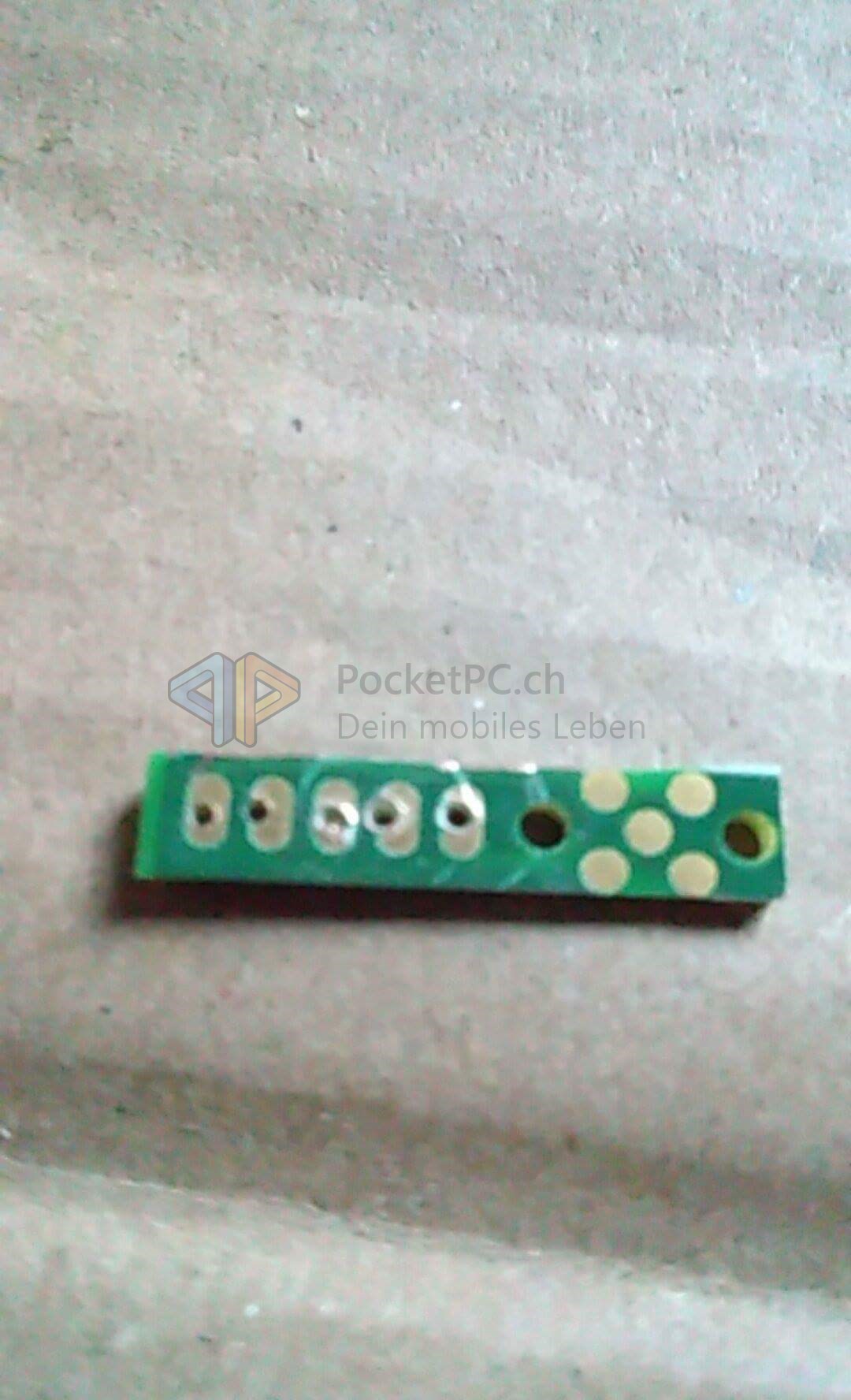
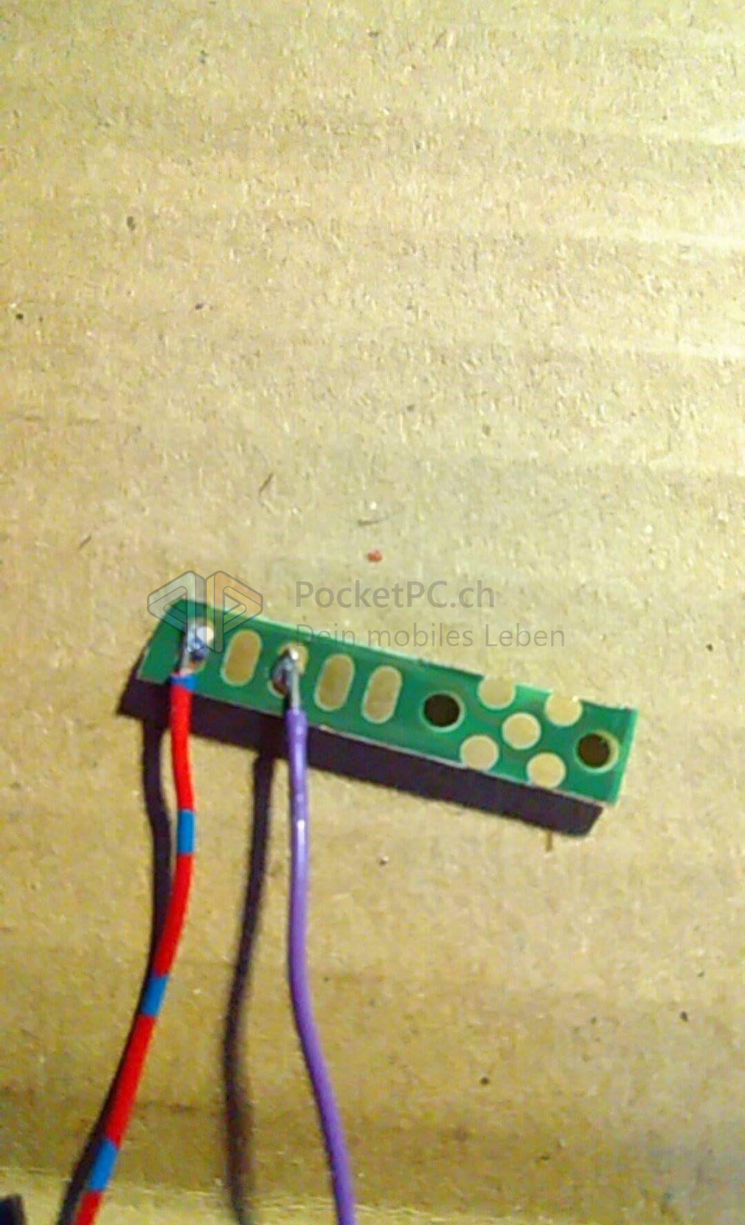
here I soldered to wires to the downside. I need only to pins: 3 and 5 (gnd and vcc)
I found the perfect holders for the connector. I make them from wooden toothpicks:
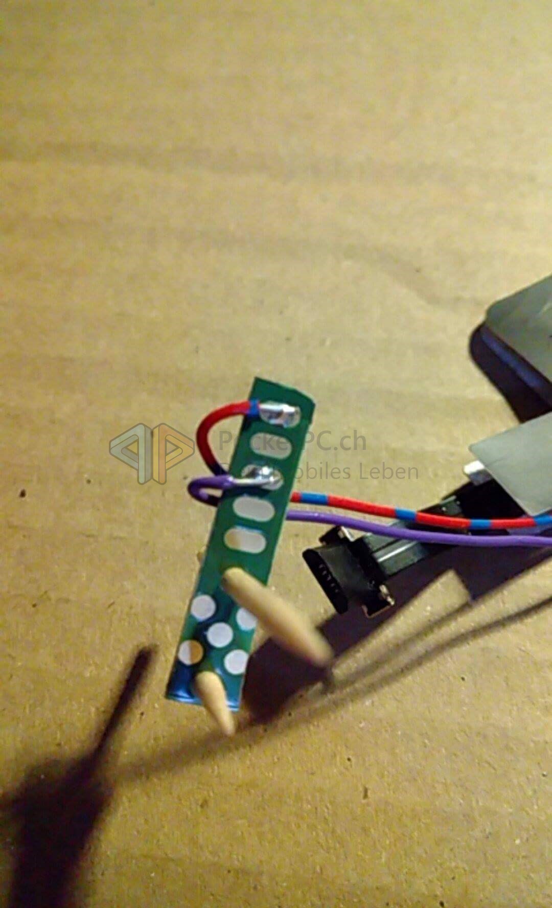
and this is how it looks like after some cutting with the swiss army knife (literally):

it fits quite well underneath the regular back cover and holds in place. if you are worried, use some adhesive insulating tape above it.
here you may see, it does not provide the best current, but still it is working:

8 Likes
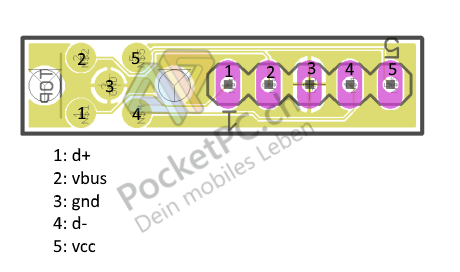
and here is the pinout to the connector. it is as stated before nearly all based on the work of dirkvl: https://github.com/dirkvl/FairPhone
it is a full fledged usb 2.0 port and i am currently tampering with it in other projects, e.g. a memorycard reader and a usb connector. maybe a slideout keyboard would also be an option?
10 Likes
so, I am thinking of how to distribute these boards to the hackers and makers around here. manufacturing costs per pcb are about 0,55 € so pretty low. I got about 80 to share with you, so what would be an acceptable way to do so? I thought of setting up a small script you can just enter your shipping address, send me manufacturing costs plus shipping and I send it to you as soon as I could, but is there anything as international and easy as paypal but fairer?
8 Likes
Bank transfer? (20 chars)
SEPA bank transfer or Bitcoin.
Just don’t rely on just bank transfer. For example, UK bank charges for sending money abroad are terrible. If I were to buy something that cost €1 and pay by bank transfer, it would end up costing me around €29 if I didn’t use an intermediary. (Okay, since SEPA this could be done for ~€18 with a lot of hassle, awful exchange rate mark-ups and still the risk that they’d charge the higher cost anyway).
That might not improve after negotiations with the EU are finished…
1 Like
Perhaps slightly off-topic, but HSBC charges £4 for a SEPA transfer abroad and an exchange rate that’s about 5% above the real exchange rate. Granted, this is still criminally expensive, but not €29. If you intend to transfer money abroad more than incidentally, take a look at Revolut or Monzo.
would everyone be happy with btc?
1 Like
I would. ![]()
![]()
I was wondering: Is this charging current normal for QI charging, or do native QI implementations charge faster?
Edit: According to this xda post it matters, which cable you use to connect the QI charger. The QI chargers tested at xda all have a nominal output current of 1A, and their actual highest charging current is about 770 mA (up to ~77% efficiency).
@jayy What was the setup for your testing environment? Did you connect the QI charger to a USB port on your PC?
1 Like
The Qi-charger is on a 5 usb port 1.2 A power outlet so the current should be fine, but I guess the Qi adapter is just cheap crap. I tested it with the built in USB cable and it did not get more than 500 mA. So I will tamper a bit with the Qi receiver, it has more than two outlets as you may see on the pictures. I will also try to get better receiver pads.
2 Likes
So, some news after a while, I got a bunch of work at my daytime job therefore was pretty much afk. But now I just finished another Qi receiver to send it to the #efct17 which I unfortunately cannot attend this time. Those of you interested in my PCB for prototyping, please drop me a message and we will find a way to send them to you.
4 Likes
@fulljionslly what you mean leave from the forum? I am still here (?) and willing to share these prototypes to anyone who’s interested
2 Likes
I would have opted for a simple dice face layout mirroring the pins with a passthrough to the back to solder or tighten cables with a screw.
1 Like
yeah, also an idea. I thought it would be more useful like this for experimenting when you have a passthrough
1 Like