Perhaps slightly off-topic, but HSBC charges £4 for a SEPA transfer abroad and an exchange rate that’s about 5% above the real exchange rate. Granted, this is still criminally expensive, but not €29. If you intend to transfer money abroad more than incidentally, take a look at Revolut or Monzo.
would everyone be happy with btc?
I would. ![]()
![]()
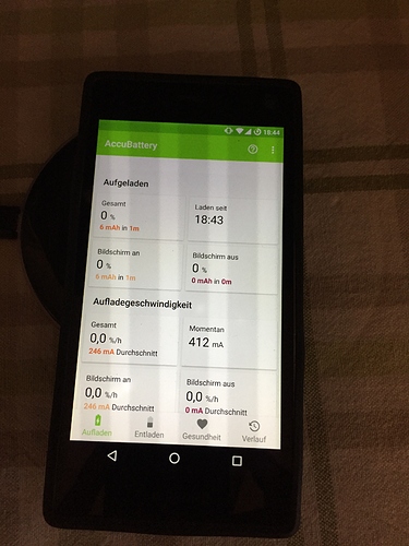
I was wondering: Is this charging current normal for QI charging, or do native QI implementations charge faster?
Edit: According to this xda post it matters, which cable you use to connect the QI charger. The QI chargers tested at xda all have a nominal output current of 1A, and their actual highest charging current is about 770 mA (up to ~77% efficiency).
@jayy What was the setup for your testing environment? Did you connect the QI charger to a USB port on your PC?
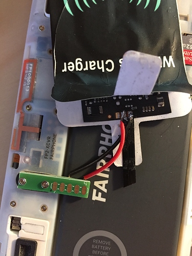
The Qi-charger is on a 5 usb port 1.2 A power outlet so the current should be fine, but I guess the Qi adapter is just cheap crap. I tested it with the built in USB cable and it did not get more than 500 mA. So I will tamper a bit with the Qi receiver, it has more than two outlets as you may see on the pictures. I will also try to get better receiver pads.
So, some news after a while, I got a bunch of work at my daytime job therefore was pretty much afk. But now I just finished another Qi receiver to send it to the #efct17 which I unfortunately cannot attend this time. Those of you interested in my PCB for prototyping, please drop me a message and we will find a way to send them to you.
@fulljionslly what you mean leave from the forum? I am still here (?) and willing to share these prototypes to anyone who’s interested
I would have opted for a simple dice face layout mirroring the pins with a passthrough to the back to solder or tighten cables with a screw.
yeah, also an idea. I thought it would be more useful like this for experimenting when you have a passthrough
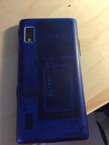
Thanks to @jayy (thanks for the fast shipping to me  ) I also have some PBCs to test with the QI chargers. I soldered the QI adapter to the PCB and used the screws from FP2 to fix the PCB to the phone.
Charging up to 420 mA. Not stable, but good enough for loading over night. Makes the Phone slightly bigger so I had to sink the screws a little bit in the PCB (not in the photos). Still a little bit to thick for the case but mostly ok.
One problem that I am facing with this: You are not able to remove the battary without unscrew the PCB.
great hack, thanks for the photos. Well, if you use the screws to fix the pcb, another design would be more favorable. maybe just the five pins with a passthrough
this is my wish. At least until someone finds a purpose printed coil card like the samsung S3 sheets.
Great project!! Wouldn`t a thinner pcb solve the problem or maybe you could use those flexible pcbs instead?
@jayy was so friendly to send me some PCBs as well and i have all the stuff here, but could not make time to assemble them.
I noticed that the PCB indeed strech the slim-cover of the FP2 to the limits, but you can force it over if you want. But i wanted to print a custom cover anyway … so *meh*…
there really should be thinner PCBs than that hackboard. all we need are contacts to weld the cabling on.
I keep saying that I have pestered a coworker with a smasung S3 to let me look at its pinout but in the end it doesnt fit.
The only solution I see is to actually out-chinese the chinese manufacturers, reverse engineer and rebuild their cards to fit directly onto the pins with insulation.
Hi @jayy, I’d like to buy one! (for my scraptop project, just got the original touchpad working, yay!) Is that possible? I live in NL, postage should be doable.
you got a message. .
This topic was automatically closed 182 days after the last reply. New replies are no longer allowed.


