Hi Luca -
See the layout for the USB test points and the debug connector on the FP2 main PCBA:
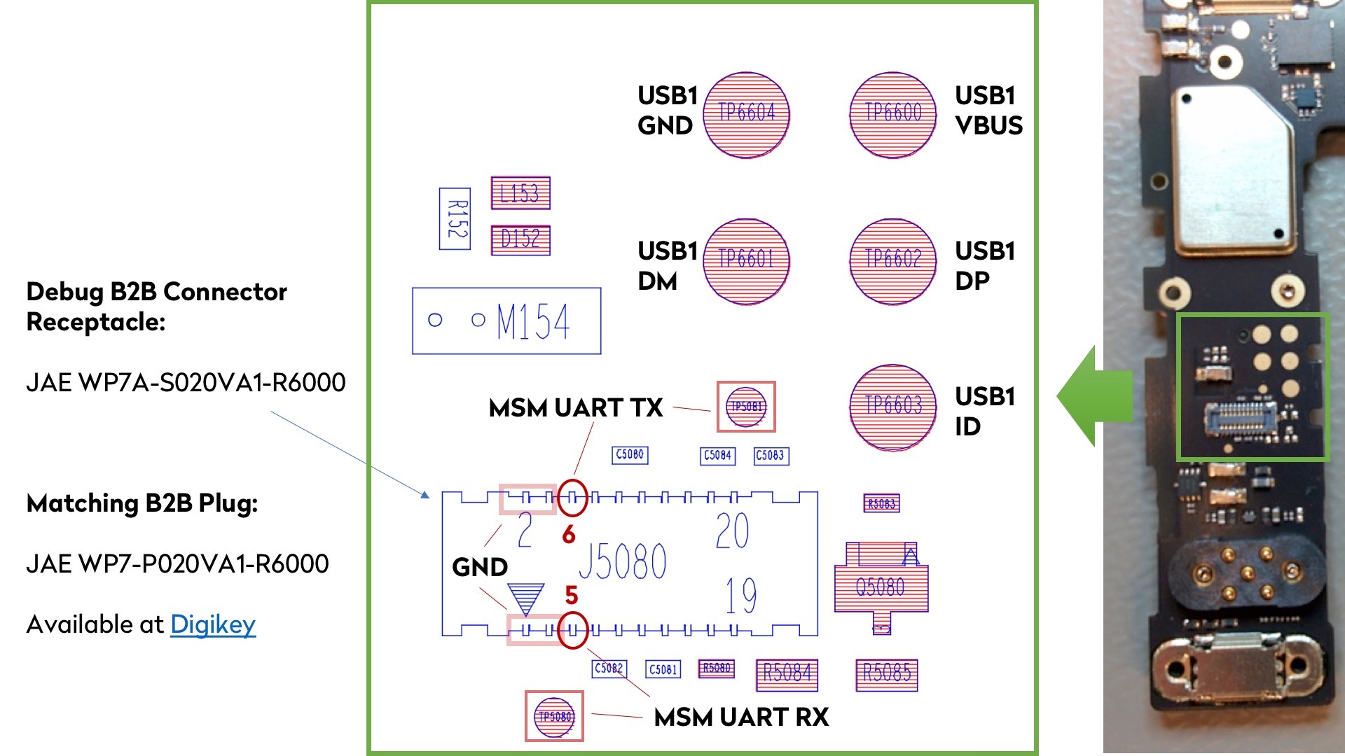
The debug UART console is routed both to two test points and to the B2B connector. I have included the reference of the connector and the matching plug. You can order those at Digikey (and you can get just a few, not a full reel of 6k units).
The USB test points are simply pads that expose the USB1 port that is going down the length of the PCB to the bottom modular connector.
This is used to access the USB port after assembly of the PCBAs in the set of flashing, test and calibration stations. The fixtures simply have a set of spring contacts to touch those pads for accessing the USB port. See picture here of the first station after the PCB panels have been assembled, de-paneled, and inspected - that’s the flashing station where we program the content of the eMMC:

We happen to have some stock of the chassis. Send me a private message and we’ll try to sort you out.
(FYI - the small PCB with the RF cable routed on the side is only the antenna feed board, the actual antennas are all on the chassis).
Cheers
Olivier