I have disassembled my phone (which was really easy, thank you ) and want to connect a cable to it to get the kernel messages out of the phone. Quote from keesj from the IRC (a while back, when I asked about last_kmsg):
< keesj> I normally use a serial
So that’s basically all the information I have about that port…
And one last question (only applies when I get some information about that debug port^^): Can I buy just the outer plastic shell, so basically the “Core module” without everything you can screw out? Like that (except the antenna):
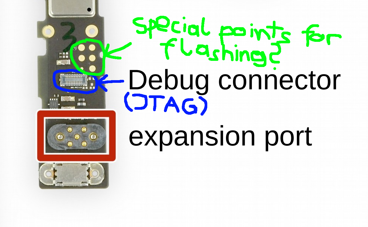
Hey, I’m not an expert either but I can give some clarification concerning what you labeled “special points for flashing?”:
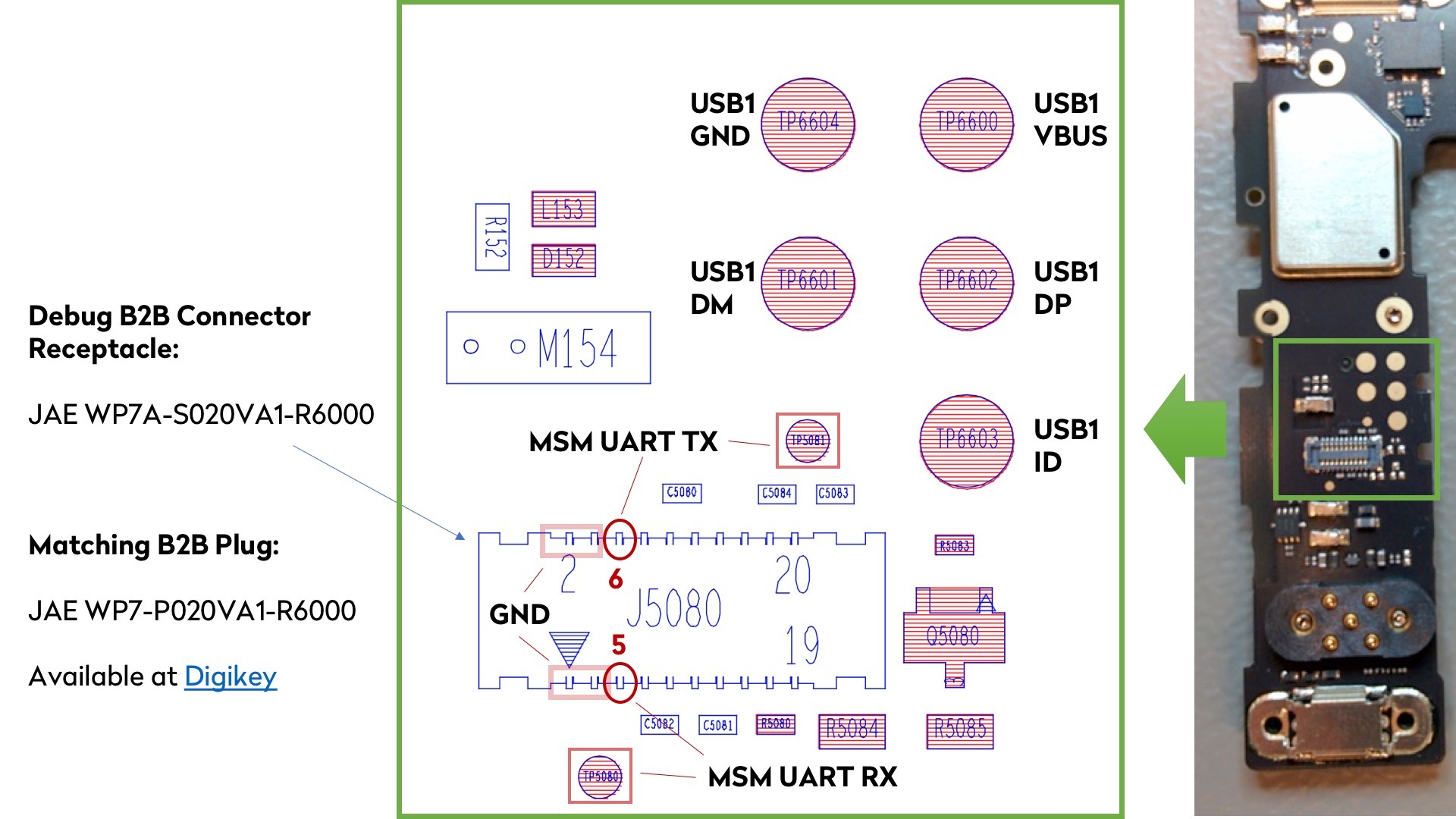
They are what Kees referred to when he talked about using a serial connection. You can solder Rx and Tx to two of these connectors and attach a serial to it. That way you can connect a serial console to the phone without relying on screen for input and output. Unfortunately I have never done this myself and do not know what points to connect to, nor what baudrate to use, etc.
The debug UART console is routed both to two test points and to the B2B connector. I have included the reference of the connector and the matching plug. You can order those at Digikey (and you can get just a few, not a full reel of 6k units).
The USB test points are simply pads that expose the USB1 port that is going down the length of the PCB to the bottom modular connector.
This is used to access the USB port after assembly of the PCBAs in the set of flashing, test and calibration stations. The fixtures simply have a set of spring contacts to touch those pads for accessing the USB port. See picture here of the first station after the PCB panels have been assembled, de-paneled, and inspected - that’s the flashing station where we program the content of the eMMC:
EDIT: I have ordered the part from the latter link. The JAE WP7-P020VA1-R6000 is out of stock on digikey and on mouser… Any idea where to get it else from? EDIT: Apparently the Rxxxx number is the Reel Part Number (see footnote) number so that part is also the correct one, right?
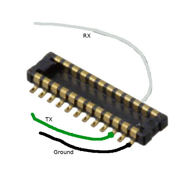
So when then have that “plug”, I solder 3 cables to it, like that and plug it into the counterpart on the phone?
sorry for the potato photo, it was taken by an iPod touch
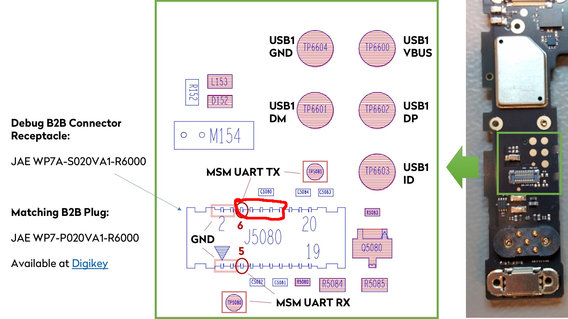
Then I held a creation out of paper clips and male->female jumper wires (as I didn’t have any others ) to the pad which is labeled as MSM UART TX in @anon65928744 s schematic. I connected this cabel monstrosity to a ‘USB to TTL UART Converter’ (converter ground->usb ground; converter RX->fairphone TX) and entered sudo screen /dev/ttyUSB0 115200 into my terminal. During the bootup process I received messages like this:
I still have to find a better solution than using both of my hands to hold cables very steady on the correct position to get messages but it’s the first step
I would suggest using “Fädeldraht” (, I dont’t know the english word, but the device it comes out is obviously called wiring pencil), it’s thin copper wire isolated with a temperature-sensitive isolation. When you solder it, the isolation burns away. It’s how we fix small bugs on our PCBs at work.
If you solder with Fädeldraht on the pads at the PCB and some kind of header (2.54 mm) on the other side, you can easily connect your serial cable for debugging.
You can glue that header somewhere with hot glue.
Quick question: Are the other pins on the b2b connector used or can I ‘solder them together’? That connector is so small but I don’t want to risk a short circuit.
 ) and want to connect a cable to it to get the kernel messages out of the phone. Quote from keesj from the IRC (a while back, when I asked about
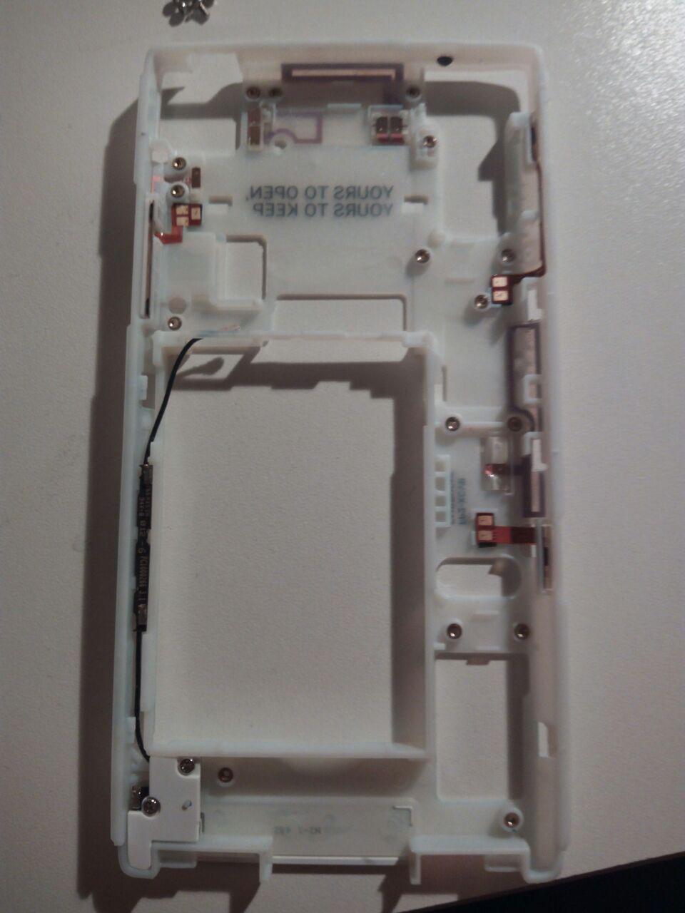


 )
) 
 ) to the pad which is labeled as MSM UART TX in
