I’m currently drawing scematics for CPU power supply, but because this is all subject to change, I can’t release renders just jet, beacuse there will be a lot of changes in this section of the board.

I like your subtle progress in the background popping up once in a while with results and not only bla - bla bla. That’s not very common these days.
Many thanks for keeping us updated.
Thanks for that feedback. I can post more renders when I’m certain that the renders won’t change too much.
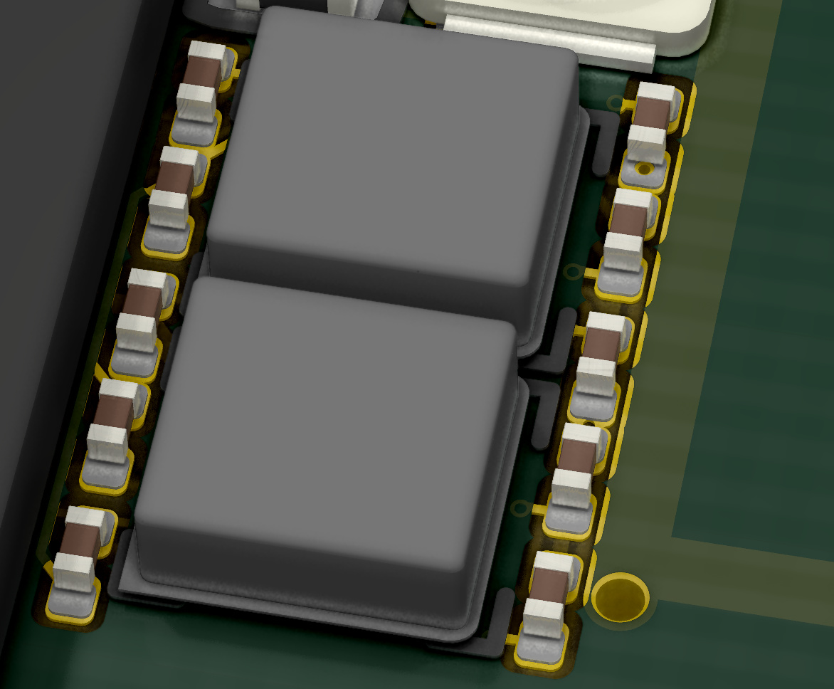
I added an underfill-like glue around the antana connetctors to prevent damage when removing the connectors. It has a rubber like consistency and is easy to remove when the device has to be serviced (component level), but prevents damage to the anatana tuning components, a damage that’s hard and expensive to repair.

Do you really need a BIOS? Most ARM chips don’t need one, but I can understand it makes OS development easier.
On Android, you have the Recovery ROM that you can use to prevent bricking (to some extent). From what I understand, it’s just booting to a different address than the System ROM.
It’s important that you have a BIOS when you want the device to be able to run linux. It also makes it easier to diagnose faults. E.g. the SMC could have a programm running that checks RAM and other important informations and reports if there is something wrong with the system over the JTAG connector. The SMC doesn’t have that much storage, but it needs to be able to check a lot of power rails and needs to be able to set the PWROK signals before the CPU even starts. And when developing a BIOS it could happen that you accedently brick the device when you only have one BIOS.
I run Linux on FPGA chips without BIOS (Xilinx Zynq), but it’s true it’s a lot of pain less if “something” can check power, memory, and other hardware stuff.
I remember “bricking” a motherboard flashing a wrong BIOS version so I’ll definitely won’t argue about a second chip 
And I trust your judgment if you think it can be laid out without requiring too much additional power, or € 
The NOR flash ICs cost only around 5€ and the are from good quality, made by winbond and they also consume just 1mA and that’s under full operation. The SMC can even write/read them at the same time
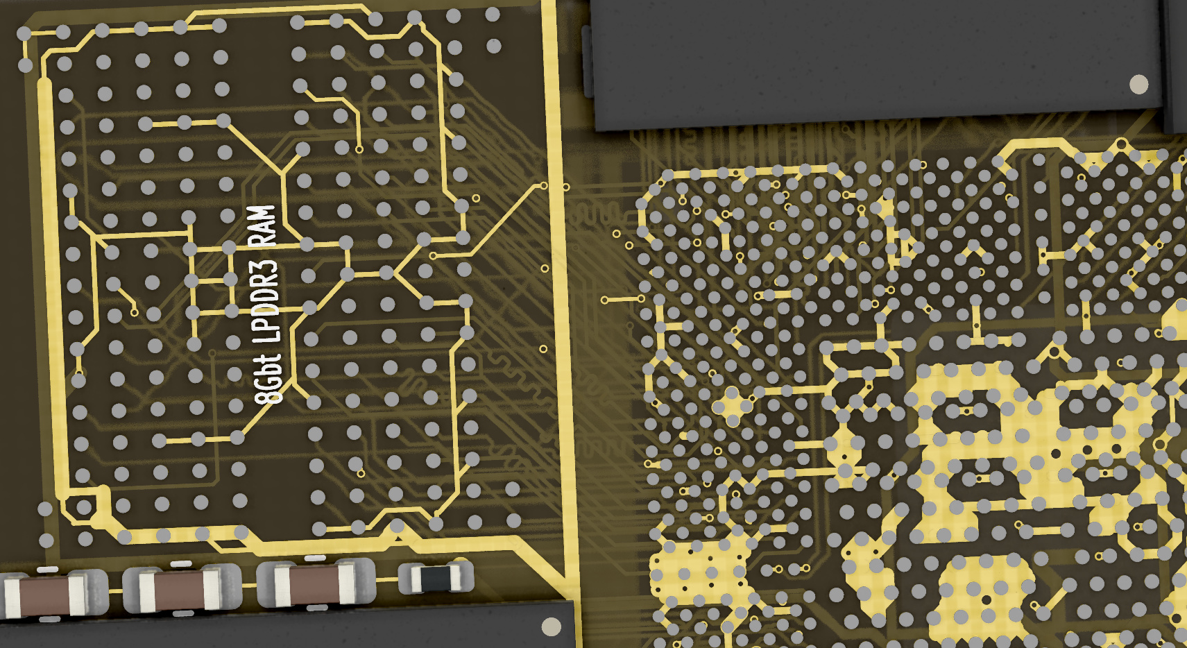
Here is a view of the board without soldermask so that it appears semi-transparent. Be aware that this is for show-purpose only, beacuse such a transparent board is impossible to manufacture. But it shows all the traces in the PCB.

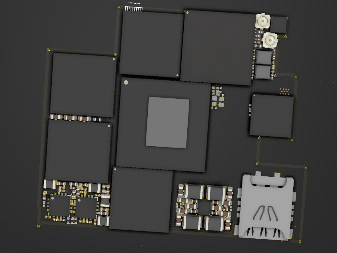
And in this render I removed one RAM chip and the CPU to expose the traces for the RAM signals
I now start to get to the point where I’m almost finished and maybe some of you know somebody that can look over it. I think there are quite some things I did wrong, so my next stept would be to let sb have a look at the whole board. If somebody likes to look over it, I can send him the files, I did everything in KiCat, but KiCat if free and opensource and even available on Windows and Linux.
It would be great if someone knew sb at fairphone, because I still need some help with my design, so every help is needed to complete this project.
Have you tried at these channels?
There is at least one Fairphone employee lurking around. ![]()
I talked to them and they were interested, but I need to talk an engineer at fairphone, because I need some technical help and some dimensions of the PCB.
@Leo_TheCrafter any news on the support through the Fairphone team?
Could update the OP we the current hardware specifications as this thread got quite long and I reckon only daily users know all details
Thx, for your request.
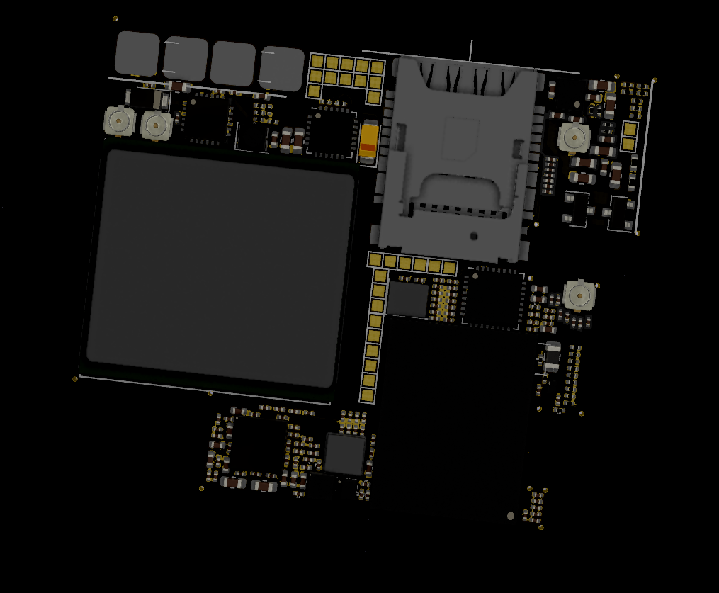
Here are the detailed specifications:
-
Intel Atom x7-z8750
-
8Gb LPDDR3 800mHz
-
Sierra Wireless AirPrime WP7607 Cat-4 LTE
-
Texas Instruments WL1837MODGI WiFi+BLE
-
128Gb Micron eMMC
-
Microchip MEC1703 SMC
-
Texas Instruments TLV320AIC3212 Audio IC
-
Molex SIM + SIM/MicroSD Combo
-
Texas Instruments LP8758-E0 CPU Buck converter
-
Texas Instruments BQ25601 Charging IC
-
Texas Instruments BQ51025 QI WPC compilant charger
-
2x Texas Instruments LM26420 Buck converters for siderails
-
2x Winbond W25Q64FW BIOS/UEFI
These are all the important ICs on the board.
Thanks for reminding me
@Leo_TheCrafter just saw your reference to your post in answer to my request
![]() great, I just some little questions
great, I just some little questions
that means that you either use 2 SIMS or one SIM plus MicroSD, don’t you?
what about GPS?
btw. how do you get along with the Fairphone guys? The posts in Why I won't buy a Fairphone - #25 don’t sound that promising?
I used one SIM slot and one connector that can handle 1 SIM and 1MicroSD, both at the same time.
The module has got GNSS, GPS, Galileo and Beidou support.
There are a lot of posts, can you please quote that specific post ?