It might have been a bit too short in the oven as 180 is a bit low, from what I read 200 for 10-15min was the initial recommendation coming from FP2 experience.
My FP3 died suddenly after 4 years. The oven reflow brought it back to life.
I let it 8 minutes at 200°C, and then let it cool down with the door barely opened.
I did it in my kitchen, and did not experience any smell. But that’s just my experience.
I put the motherboard on a silicone plate, not to create any hot point while heating up.
It’s been only few days now. I hope I will last a few more years now.
Thank you for the helpful thread!
2 Likes
Thank you for compiling all this! It’s really helpful.
My Fairphone 3 sadly experienced a sudden death a couple weeks ago. I’ve been looking for possible ways to fix it. I have access to a heat gun but not a heatplate. In the video it seems he doesn’t use one but I couldn’t quite tell. Do I definitely need a heatplate?
Hello,
the heatplate is really important. The rationale is that too big differences in temperature from one side of the motherboard to the other can induce material problems (uncontrolled thermal expansion, crackling, spurting). So the “ramp” phase is used to bring the whole motherboard to a sub-melting temperature homogeneously, to avoid big temperature differences.
In the video, i think he puts the phone on a heatplate and uses a heatgun.
From my perspective, you certainly need one to expect the best possible result.
I think in most cases a ceramic honeycomb soldering plate will reduce the thermal lost of the back to acceptable level - especially for DIY use.
1 Like
Chiming in here with a bit of background since I have been learning about soldering and BGA rework in the last year or so. I’m definitely not an expert yet, but I have some understanding of the basics, so hopefully this will help and if I’m wrong, true experts, please feel free to chime in and correct me ![]() …
…
The main problem with modern printed circuit boards (PCBs from now on) and the ball grid array format (BGA from now on, e.g. used in bigger components like RAM chips - very roughly speaking a lot of solder balls underneath the chip) is that solder balls can crack if the PCB is under tension, causing broken (“cold”) solder joints underneath the chips. This seems to be the a bigger problem nowadays than a few years back, since, in order to avoid toxic materials, manufacturers have switched to lead free solder alloys. Since the metals used are less soft and flexible than lead, solder joints seem to have become somewhat more brittle. I personally have no opinion on whether to use leaded solder and this is flamewar turf, so let’s stay on the main topic ![]() …
…
Among the main sources of failure in a PCB are either cracked solder balls or a ceramic SMD capacitor that has cracked and causes a short circuit. These capacitors are rectangular and beige in color and have a solder pad on both sides. Cracked capacitors need to be replaced in order to fix the problem and a reflow will not help. I am not surprised that RAM chips etc. fail most often - the more area a chip covers, the more tension can build and crack a solder joint.
In some cases you can test for cracked balls by gently pressing the chip down (try not to bend the board), then powering the board on while keeping it pressed. This is sometimes enough to re-establish contacts and could be an indication which chip has problems. I’ve had very mixed success with this though.
Cracked solder balls can, in theory, be reflowed as was already discussed, but many electronics repair people tend to be skeptical about the reliabilty of the approach and how long it will last if it works.
This brings us to the role of flux. While some posters have already mentioned some aspects of this I thought I’d sum it up in a single paragraph: Flux basically is a substance that is very acidic and usually get more reactive and fluid under heat. It will remove any layers of oxidation that naturally form on bare metal surfaces. These oxidation layers prevent the solder from sticking to the contacts and reduce the surface tension of liquid solder. Flux helps solder to flow freely and to wet the contacts well. (This is why it’s called flux, think “flow”). Flux will prevent solder bridges (i.e. unwanted contacts) from forming when reflowing a chip, since the solder will keep its compact ball shape and will stick very well to the pads/contacts instead of clotting.
I would say that flux is vital for any kind of soldering and especially reflowing/reballing.
Back to reflowing: The problem with BGAs is that you cannot visually check whether it worked, since the balls are hidden under the chip, so you will have limited feedback on what you did. If you still decide you do want to try reflowing a single BGA chip, put a bit of flux to one or two of its sides, then let it flow under the chip during heating. Don’t use too much, since the chip might float too much on the flux. The flux will flow under the chip due to capillary effects.
Potentially cover things you want to keep cool like plastic elements or sensitive components with e.g. tin foil. Most people set their temperature to around 350°C and medium to higher airflow, but this is very dependent on the power of the gun.
If you don’t have a hot plate, this is not a huge problem for small PCBs like the ones on phones, just make sure to first warm up the board evenly by moving the hot air gun over it. Slowly bring the board up to ca 120° then start focusing more on the chip you want to replace. Still keep the hot air nozzle moving a bit to spread the heat into the board and not only heat the chip alone. You can test whether the solder has melted by very(!!) gently tapping the chip from the side with tweezers etc. If the solder has melted, the chip will move a bit, but the strong surface tension of the solder will pull it right back in place. In order to give the solder balls a chance to mend, you might want to tap the chip from the top, but also very(!) gently. Otherwise the pressure might cause the balls to stretch and link causing a solder bridge.
Here is a video of Sorin from Electronics Repair School reflowing a BGA chip. He makes it look easy.
Here is a video where Richard from Learn Electronics Repair gives more background on the basics of removing BGA chips. This is basically what you do during a reflow, except instead of removing the chip, you just melt the solder (and maybe gently(!) tap it) then let it cool again.
I never tried oven reflowing and the cheaper ones probably don’t have support for heating profile curves. Even if they do, you don’t know the manufacturers profiles, so this will not help too much. As others mentioned, reflowing in a kitchen oven should really be avoided. There are a lot of toxic materials around that might stick to the oven walls for a long time and poison your food - even if you can’t smell them. Most fluxes will smoke heavily at higher temperatures. even if you don’t apply any, there will be residues on the board.
Generally speaking, modern lead free solders often have higher melting points (around 230°C) than leaded solder (around 190°). The exact temperature depends heavily on the alloy used by the manufacturer, so if you want to do an oven reflow I’d guess that anything under 230° is not going to do much except stress your board and components.
The cleanest method would be a reball instead, which is removing the chip using a hot air gun, then removing the old solder ball residues from board and chip, fitting new balls on the chip and soldering the chip back on with hot air and a little flux. This is quite difficult and requires experience. If you want to try this, I’d recommend getting a scrap board with a couple of BGA ICs and practicing by removing and refitting a few times. Getting this right as a beginner the first time is not very likely.
Here is a video of someone reballing a GPU, after removal. For RAM chips you won’t really need a stencil, since they have much fewer balls. And you don’t need such a big nozzle for RAM chips. I’ve already refitted a RAM chip by hand and it’s not too time consuming. You’ll probably need a magnifying glass though.
If you are a real pro, with a steady hand you can try removing and refitting the chip without replacing the solder, but this is much(!) harder than it looks and might lead to unreliable results.
Here is an example of Sorin of Electronics Repair School doing this.
I hope this provided some more background and is helpful for some of you.
Good luck with the repair attempts ![]()
11 Likes
Great insights, NickNougat!
Concerning the use of the heatgun without heatplate, your proposition makes sense.
I must now let you know about my first oven reflow attempt on a test device (FP3+).
I regret to report that it was a failure.
I purchased it as is some months ago, presumed victim of a sudden death. Tested plugging in. Tested with other modules. No reaction at all.
After thorough disassembly, here is the protocol:

12 min @ 200°C (command temperature, not measured)

05 min @ 230°C (command temperature, not measured)
I heard some noise coming out of the device, some sizzling/popping noise.
11 min cooldown in oven with door open.

10 min cooldown out of oven.
The device was lukewarm when I touched it. It was visibly discolored.
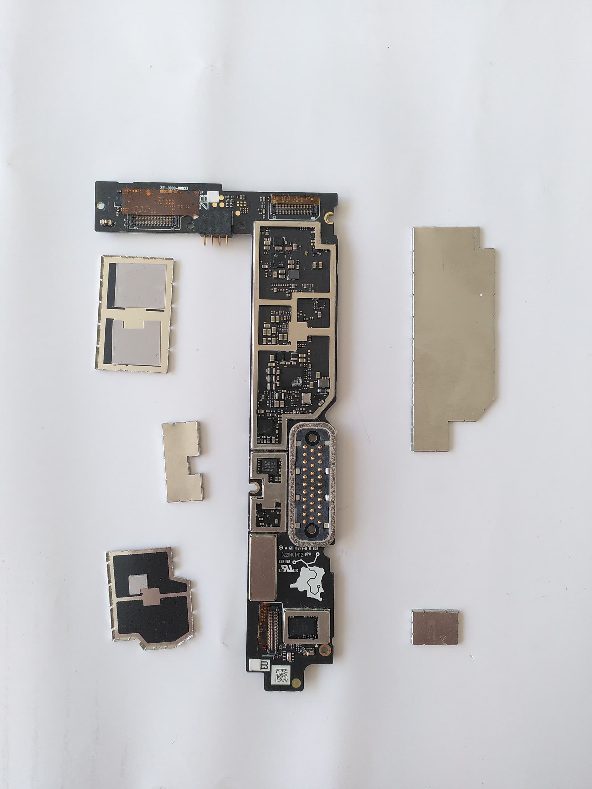
I observed something on the tray when I took it out of the oven (some component? I couldn’t find where it was supposed to be).

No reaction to being plugged in as a test with only the bottom module (which is functional, the writing on the module is just an identifier).

I tried it again this time with a bit longer spike. Nothing, again.
Maybe the ramp period was too long. I am not familiar with that model of oven, so I thought the light indicated pre-heating. I wanted to make sure the oven was indeed at 200°C before going ahead. But it just meant it was turned on.
I’m pretty disappointed with that result.
1 Like
Sorry to hear that. It’s weird that a component fell out. Usually if the solder melts, there will be “suction” due to surface tension holding stuff in place. Maybe it was already somewhat loose., or whatever caused the popping noise dislodged it. It looks like a ceramic capacitor. These are not always critical and are mostly used to make sure that no noise occurs in the circuit. The board should probably run without it, but might be more sensitive to EM. Sizzling and popping occurs mostly with electrolytic capacitors, since liquid electrolyte inside can evaporate, expand and burst free. Such components don’t like being exposed to long heat. From your pictures I can’t make out if there are such capacitors on the board, but something like that is the most likely cause of such noises. I couldn’t see anything on your picture that looks blown, though.
What I found pretty helpful is taking a picture of the PCB before working on it. If something goes wrong you can take a picture with a similar perspective again, then load them into separate layers in a paint program (e.g. the free, open source Paint.NET on Windows). Once you align and stretch the layers, to make them match you can toggle or fade one of them to see differences. If you take another picture now and compare it to your first picture, that might help you locate where that capacitor came from. That might also give you clues, what could have popped.
Generally speaking, heating up the entire PCB causes quite some stress for the components, so if you can somehow narrow down where the fault lies, I’d definitely recommend using a heat gun. For such small PCBs that aren’t too heavy on copper layers that drain heat away, even cheapo ones for under 40€ like the millions of 858D clones on Amazon and 2nd hand on flea market platforms such as WillHaben and Kleinanzeigen will do the job. They haven’t got enough power for PC mainboards or GPUs, but for small stuff they are OK in my experience.
Also, I guess for a reflow oven it might be a good idea using an oven thermometer in a test run to see how well the oven follows the temperature setting before putting anything inside. If you use it for the first time, it should even be safe to use the one you use to bake with.
Unfortunately, it only worked for a couple of weeks.
So this is a failure eventually.
It is shown as a last solution to save your data before a permanent death so this isn’t unexpected…
Hello,
My FP3+ had been charging all night and suddenly it switched off. I tried to light it up but nothing happens. I tried to remove the battery, to plug it but nothing happends. I tried to press the 3 buttons at the same time and it vibrated every 8 seconds without anything showing on screen. After that, it began to react to the power button : the “Fairphone / Powered by Android” message shows up for a few seconds. It still does that but not all the time.
Even when plugged, the LED doesn’t light up at all.
I saw a number of similar questions, with different answers, so I don’t exactly know what to do…
EDIT :
It’s now almost dead, only vibrating from time to time but no more screening.
I have a question that can seem obvious, where do you all find your heating plates or heat guns ? I want my own oven to stay usable for food in the future… Also, is there any way to get the data back without any heating thing as my phone still vibrates from times to times ?
Hi,
as the other user explained, ever day after a reflow is a chance. The first thing it’s for, ultimately, is just back up your data. The reflow job is not a profesionnal repair and offers no garantees of durability. A short period of the phone working, some days or some weeks, before dying again is documented. It doesn’t mean that it’s a failure.
as for Odysseus, i’d advise first going to recovery and try to wipe cache, then fastboot and try to access the system. It may be a software issue.
2 Likes
I tried to reflow my FP3 with a hot air gun today. It is the second time in the lifetime of my FP3 that Sudden Death occurred, so I was somewhat prepared. The first time, about a year ago, I reflowed the PMI632 PMIC, which resolved the issue. Now this time I found this forum post and tried to reflow the memory instead (the eMMC flash I guess?).
WIth a hot air gun at 200 degrees celsius for the first 15-20 minutes, then up to 370 degrees, I was not able to melt all the solder balls to actually be able to move the chip around. But after attempting to reflow the chip, I tested it and the device completely worked again. The success was shortlived though, after reassembling the plastic frame and screwing on the display, the phone was again suddendly dead. I will probably try to find a skilled professional in the area now to actually reball the PMICs and possible also the memory. Hopefully, this provides a more long-lasting fix. I wonder whether the display screws are causing inconsistent stress on the plastic case and main board.
I am not sure the eMMC flash can really cause the fault… intuitively I would expect at least the charging indicator to work without the eMMC flash, but perhaps it too does rely on some firmware stored on the eMMC flash. Another argument for the culprit being the eMMC flash is that after reassembling the phone, shortly before the Sudden Death after my repair, the phone was booting and started vibrating (as usual on startup). Then, it kept vibrating continously, without anything displayed on screen. This could mean it executed some startup code to enable the vibration, but before the rest of the code could disable the vibration, the solder balls of the eMMC cracked, severing the connection to the CPU and preventing the rest of the code from being loaded and executed. If it were a PMIC issue instead of a eMMC issue, I would expect the vibration to stop, since I assume the vibration is powered from a voltage bus provided by the PMICs. Maybe some in-depth voltage probing around the PMICs on other Sudden Death FP3’s could clear up whether those chips actually are operating correctly or not (due to broken solder joints).
The issue around sudden deaths has had an uptick recently. Freiburg heaven reports six cases just in the month of June.
1 Like
Update on my personal FP3 situation: Had eMMC and PMICs professionally reballed. The phone is still dead. Perhaps the issue lies somewhere else, like component damage.
whoa, that must have been an odyssey for that phone.
But if I counted correctly, you had reflowed it twice already before it died, which is, by my count, a success.
Because each reflow might damage other components due to thermal stress, suboptimal handling, etc.
In general, the trick doesn’t work twice or more.
Thanks for your testimony.
I used an air-gun too to reflow the memory of a user’s FP3 some weeks ago.
After various unsuccessful attempts, the one that did the trick was a bit of 200°C (1-2 min) on the greater area around the memory, and then 5 minutes @360°C on the memory itself.
It didn’t flow or move, but it worked nonetheless : the phone booted.
Apparently the camera wasn’t working, no idea why. And the phone died again some days later
2 Likes
Thank you for your help.
My FP3+ suddenly died today.
Until now, I had never heard of this sudden failure…
I am very disappointed by this kind of problem, as it clearly goes against the spirit of Fairphone.
It is clearly a very bad experience.
Reading the testimonials on this subject, it doesn’t seem like the company has really taken the problem into account. It makes you feel like you’ve been abandoned with your problem.
I’ve lost confidence in Fairphone.
So I have three possible options:
-
Repair it myself, but I don’t have the necessary skills…
-
send it in for repair, but that will cost me too much (= the price of some new smartphones…) and, above all, the problem is likely to occur again in three years…
-
look elsewhere…
To my great regret, the only viable solution is the last one…
I understand that, however in the starting post of this thread there is this quote:
If you click on that quote you’ll get to a full explanation why the author thinks so. So maybe this can recover some of the confidence…?
3 Likes